Engine-driven working machine

An engine-driven, working machine technology, applied in the directions of engine components, engine cooling, engine frame, etc., can solve problems such as large load, and achieve the effect of reducing impact load, preventing excessive deformation, and avoiding interference

Inactive Publication Date: 2008-12-17
HONDA MOTOR CO LTD
View PDF9 Cites 0 Cited by
  • Summary
  • Abstract
  • Description
  • Claims
  • Application Information

AI Technical Summary

Problems solved by technology

[0004] However, in the prior art, the limiting device and the elastic supporting parts are collectively arranged between the working unit and the lower part of the frame, so the limiting device receives a relatively large load when limiting the amplitude of the working unit, especially when carrying a large-scale working unit. unit, high strength is required
Moreover, when the working unit receives a large external force from the side, there is a tendency for the upper part of the working unit to vibrate greatly with the restraining device at the lower part as the fulcrum. large gaps, which is one of the reasons for the large size of engine-driven working machines

Method used


Image

  • Engine-driven working machine
  • Engine-driven working machine
  • Engine-driven working machine

Examples


Embodiment 1

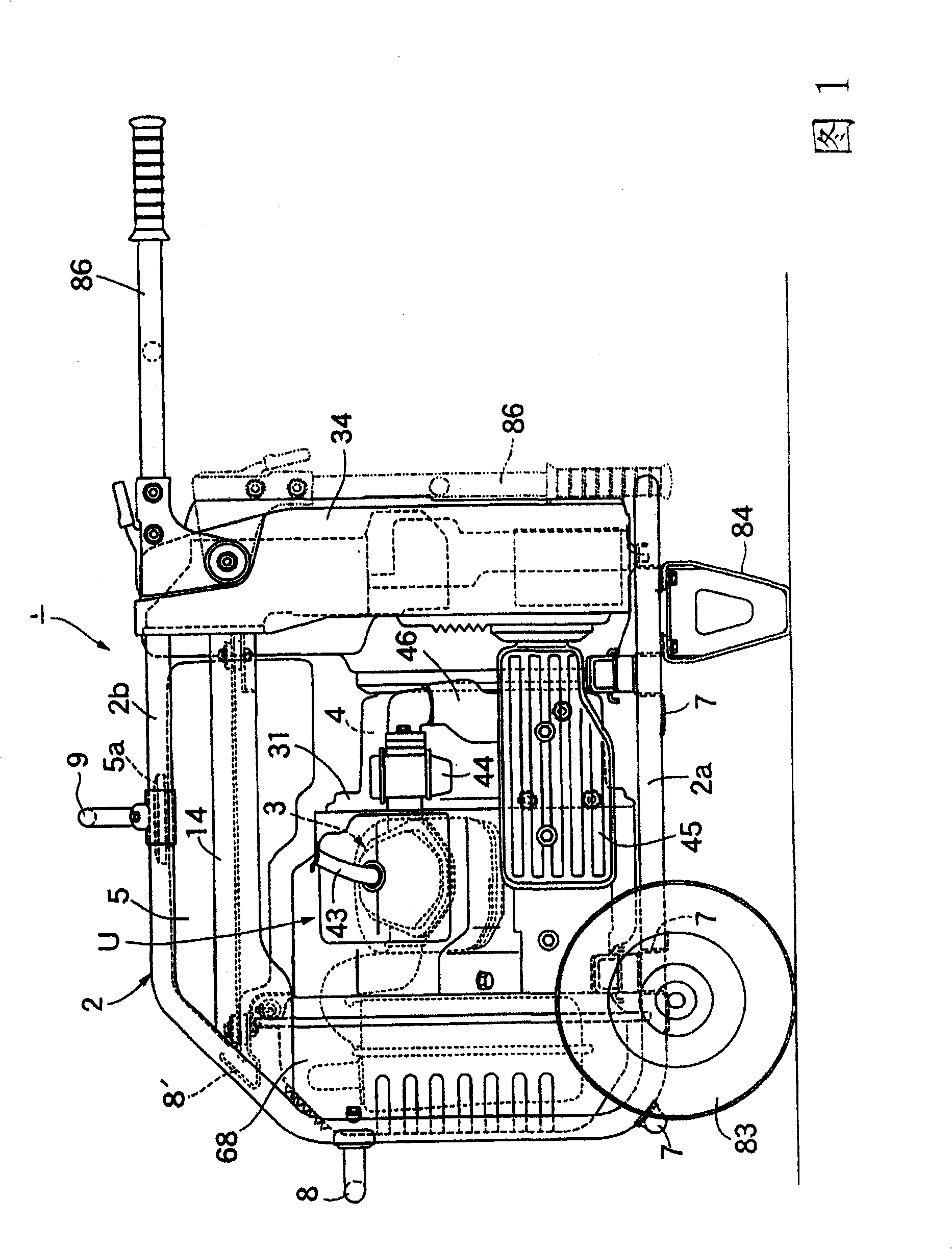
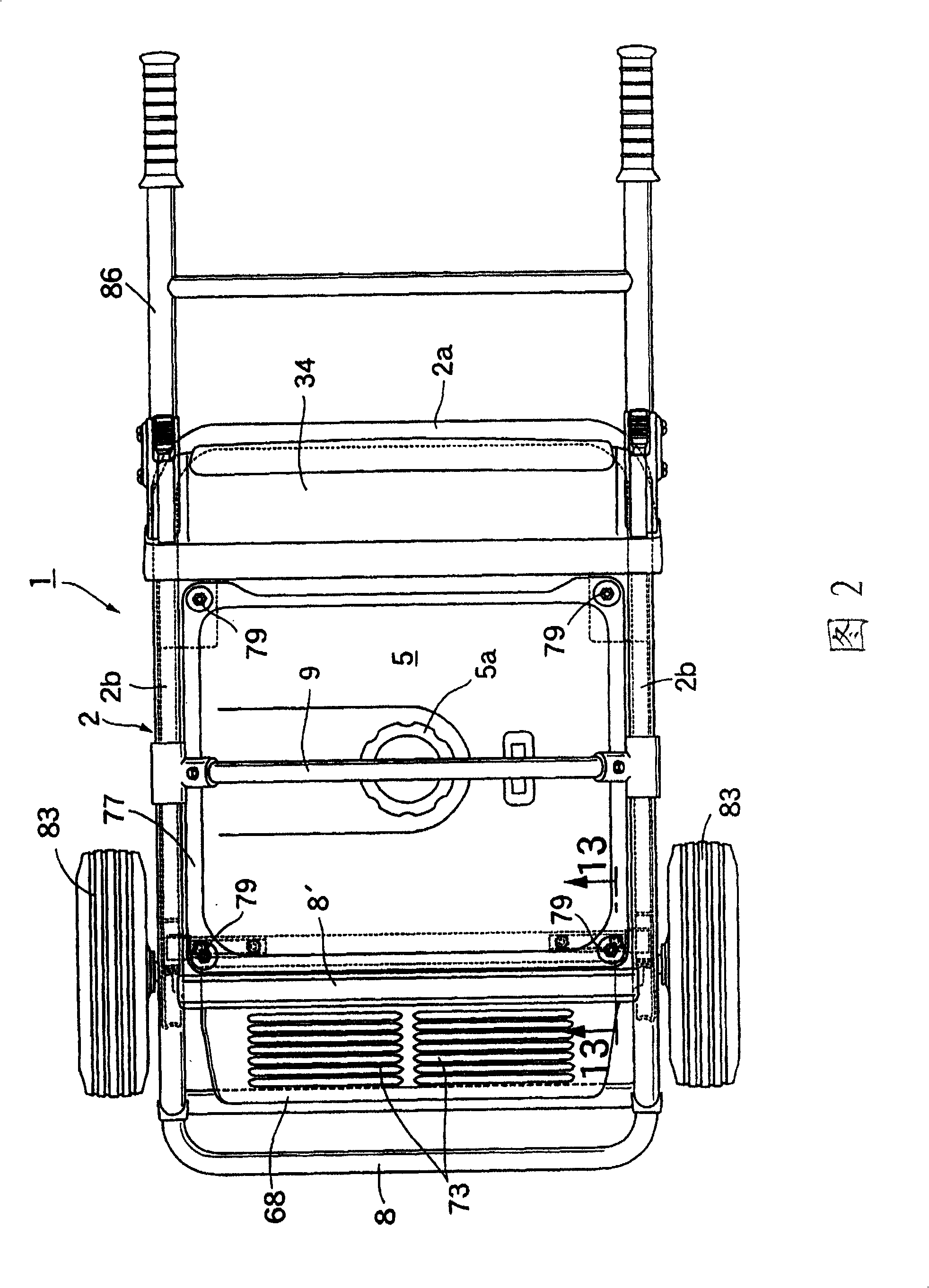
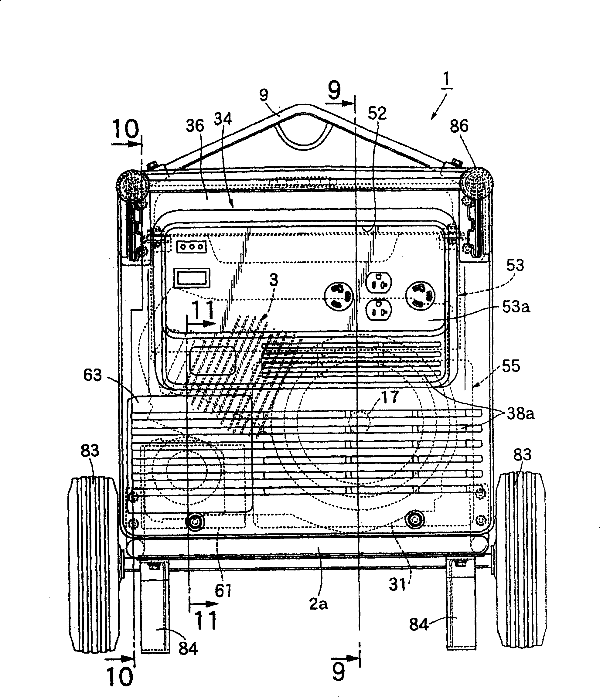
[0061] First, in Figure 1~ image 3 Among them, the engine-driven generator 1 as the engine-driven working machine of the present invention includes: a frame 2; a working unit U composed of an engine 3 and a generator 4 and elastically supported by the frame 2; fuel tank 5 in the upper part of 2; control unit 53 for engine 3 and generator 4.

[0062] Figure 1~ image 3 And as shown in FIG. 8, the frame 2 is constituted to include: a bottom frame 2a obtained by bending a steel pipe into a U-shape; It is bent horizontally and forms a U-shape together with the left and right sides of the bottom frame 2a.

[0063] A plurality of lower cross members (cross members) 7, 7 ... connected between the left and right sides are provided on the bottom frame 2a, and a connection is provided between the upper parts of the vertical sides of the two side frames 2b, 2b. The middle cross member 8 of the two side frames 2b, 2b is provided with an upper cross member 8' connecting the inclined corn...


PUM


Abstract

An engine-driven working machine, wherein elastic support members (11, 11) are installed between a lower part of a working unit (U) having an engine (3) and a frame (2) carrying the working unit (U), It is arranged below the crankshaft (17) of the engine on both sides of the vertical plane (V) passing through the axis of the crankshaft (17). In addition, a limiting device is provided between the working unit (U) and the frame (2). (122), which restricts the vibration amplitude greater than or equal to a predetermined angle around the crankshaft (17) of the working unit (U), and the limiting device (122) is arranged between the upper part of the working unit (U) and the frame (2) . Thus, even when the working unit receives a large external force from the side, it is possible to restrict the swinging of the working unit at a predetermined angle or more.

Description

technical field [0001] The present invention relates to an improvement of an engine-driven working machine, in which an engine and a working machine driven by a crankshaft of the engine are combined to form a working unit, and an elastic support member is installed in the lower part of the working unit and carried Between the frames of the working unit, it is arranged on both sides of the vertical plane passing through the axis of the crankshaft below the crankshaft. The extended way is inclined, and a limiting device is provided between the working unit and the frame, which limits the vibration amplitude of the working unit around the crankshaft that is greater than or equal to a predetermined angle. Background technique [0002] For example, such an engine-driven working machine disclosed in Patent Document 1 is already known. In such an engine-driven working machine, during the operation of the working unit, the vibration around the crankshaft can be effectively absorbed...

Claims


Application Information

Patent Timeline
Patent Type & Authority Patents(China)
IPC IPC(8): F16F15/08F16M3/00F01N13/00F01N99/00F01P5/06F16M1/00
CPCB60K5/1216F01P2001/005F01P2005/025F02B63/04F16M3/00H02K5/24H02K7/1815
Inventor 岛田裕司鹿子生浩巳
Owner HONDA MOTOR CO LTD
Why Eureka
Try Eureka