Electronic apparatus and fan thereof
A technology of electronic devices and fans, applied in pump devices, components of pumping devices for elastic fluids, cooling/ventilation/heating transformation, etc., can solve problems such as inapplicability, increased noise, and increased costs
- Summary
- Abstract
- Description
- Claims
- Application Information
AI Technical Summary
Problems solved by technology
Method used
Image

Examples
no. 1 example
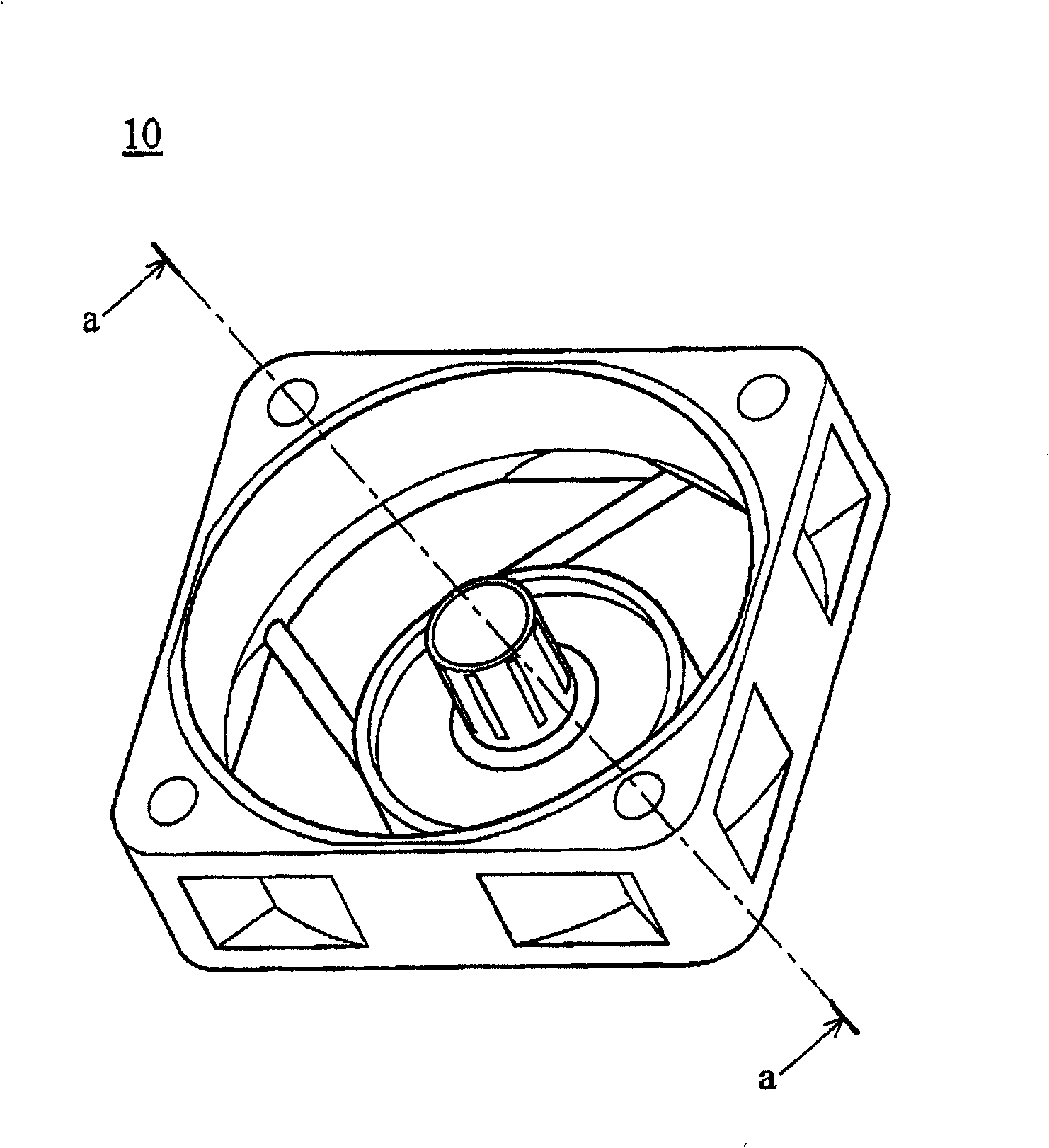
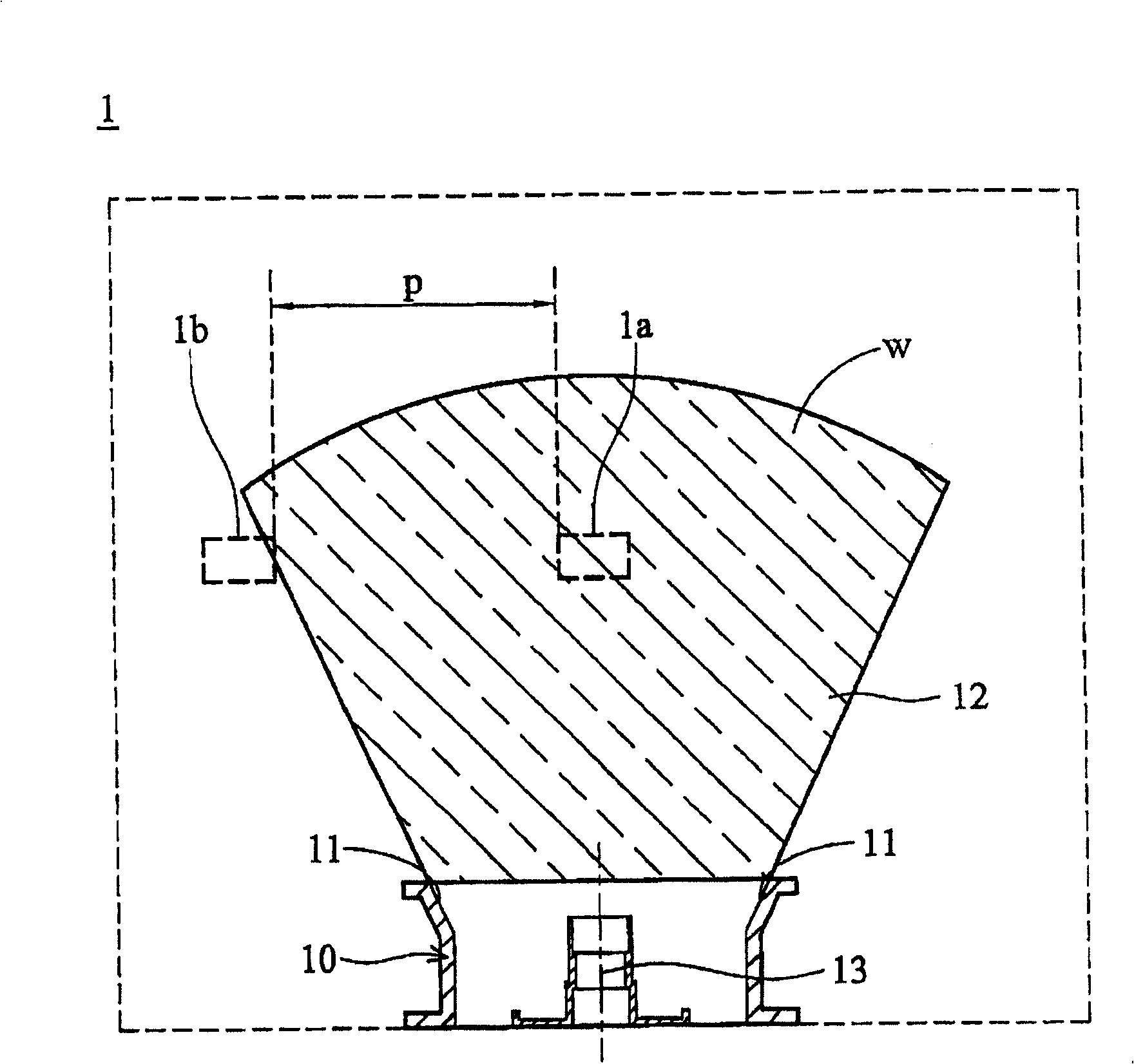
[0064] Figure 3A is a flow field schematic diagram of the electronic device according to the first embodiment of the present invention, Figure 3B ~ 3C is a schematic diagram of the fan in the first embodiment, wherein, and Figure 3C for along Figure 3B The cross-sectional view of b-b in the middle, and in order to simplify the illustration, Figure 3B ~ 3C The stator and fan blades are omitted, and only the fan frame is used.
[0065] Such as Figure 3A As shown, the electronic device 2 includes a housing 2a and a plurality of heat sources 2b, 2c, wherein the heat sources 2b, 2c and the fan 30 are all arranged in the housing 2a, because of the arrangement of the components, the heat sources 2b, 2c are dispersed from each other, and the electronic The device 2 only has an accommodating space 2d at the edge of the casing 2a where a cooling fan can be disposed. In order to meet the heat dissipation requirements in a limited space, the fan 30 of the present invention chan...
no. 2 example
[0070] Figure 4A is a flow field schematic diagram of the electronic device according to the second embodiment of the present invention, Figure 4B for Figure 4A The top view of the middle fan frame, Figure 4C for along Figure 4B The cross-sectional view of c-c in the middle, and in order to simplify the illustration, Figure 4B ~ 4C The stator and fan blades are omitted, and only the fan frame is used.
[0071] Such as Figure 4A As shown, the electronic device 3 includes a casing 3a, a main heat source 3c, a secondary heat source 3d and a fan 40, wherein the heat sources 3b, 3c and the fan 40 are all arranged in the casing 3a, and the position of the fan 40 is facing the main Heat source 3b, compare Figure 3A and Figure 4A It can be seen that since the distance D between the heat sources 3b and 3c is larger (D>p), the fan 40 has a flared portion with a larger flare angle, so that the range w of the flow field generated by it is larger, and it can be applied to e...
no. 3 example
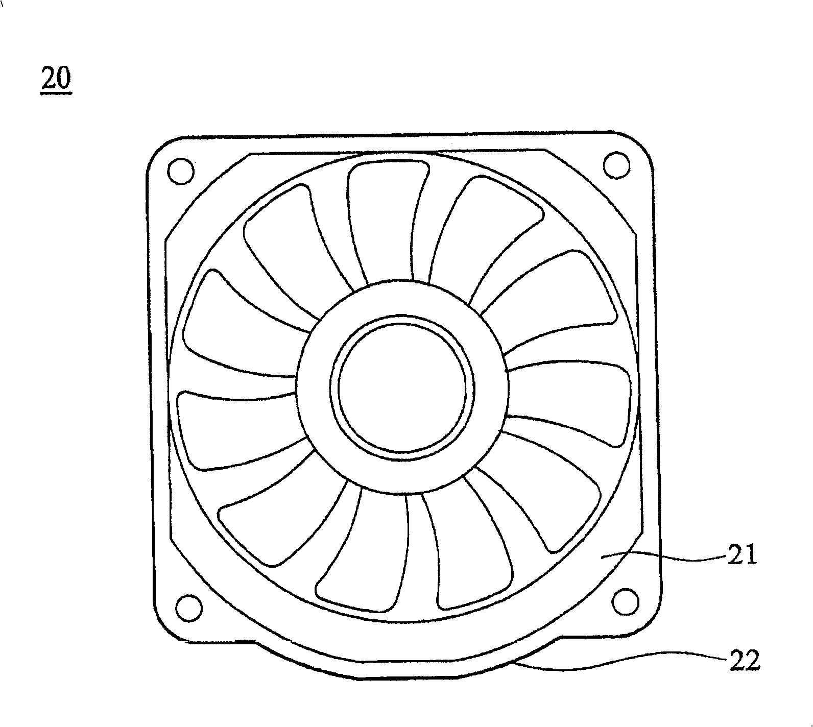
[0075] Figure 5 It is a top view of the fan according to the third embodiment of the present invention. In this embodiment, the fan 50 has a fan frame 51 and fan blades 52 , and the fan frame 51 has a flared portion 51a inside.
[0076] The difference between this embodiment and the above-mentioned embodiments is that the shape of the fan frame is trapezoidal, and the expansion part is formed along the periphery of the air outlet and the air inlet, so that the shape of the air outlet and the air inlet is roughly fan-shaped, so that it can be used in both systems. In the case of the relative position of the internal heat source and the accommodating space, the dispersed heat sources in the system are dissipated.
[0077] Figure 6 As a modification of the third embodiment, the fan frame shown has flared portions 61 a on both sides, whereby the flow field range of the fan frame can be changed to be applicable to systems with different heat sources.
PUM
 Abstract
Description
Claims
Application Information
 - R&D
- Intellectual Property
- Life Sciences
- Materials
- Tech Scout
- Unparalleled Data Quality
- Higher Quality Content
- 60% Fewer Hallucinations
Browse by: Latest US Patents, China's latest patents, Technical Efficacy Thesaurus, Application Domain, Technology Topic, Popular Technical Reports.
© 2025 PatSnap. All rights reserved.Legal|Privacy policy|Modern Slavery Act Transparency Statement|Sitemap|About US| Contact US: help@patsnap.com