Process for soldering sealing chemiluminescent tube end

A chemiluminescence, tube end technology, applied in the direction of light source, fluorescence, lighting devices, etc., can solve the problems of poor and inability to weld the open end of the chemiluminescence tube and seal the welding effect.

Inactive Publication Date: 2009-01-28
金朝阳
View PDF6 Cites 0 Cited by
  • Summary
  • Abstract
  • Description
  • Claims
  • Application Information

AI Technical Summary

Problems solved by technology

However, during the welding process of this welding method, the plug will move to the inside of the cavity and squeeze the glass core inside the cavity, breaking the glass core and extruding the chemiluminescent agent inside the cavity, making it impossible to chemiluminescent agent. The opening end of the luminous tube is welded or the sealing effect is not good

Method used


Image

  • Process for soldering sealing chemiluminescent tube end
  • Process for soldering sealing chemiluminescent tube end
  • Process for soldering sealing chemiluminescent tube end

Examples


Embodiment Construction

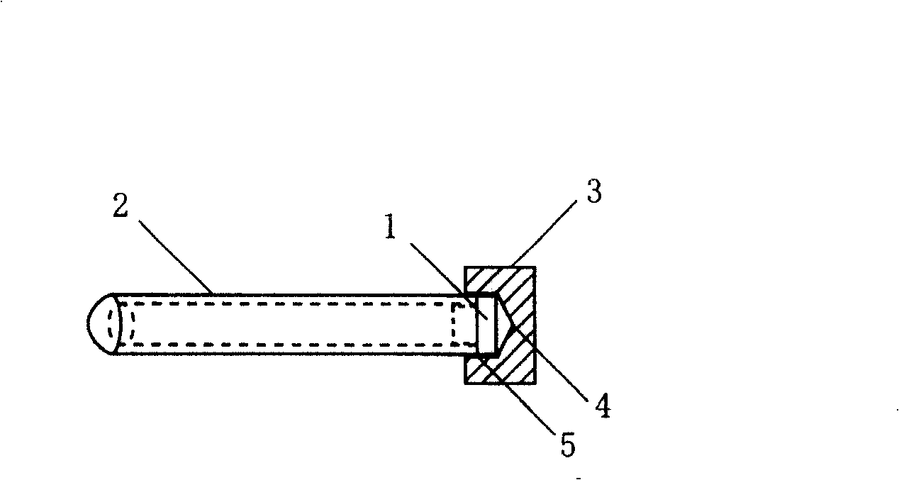
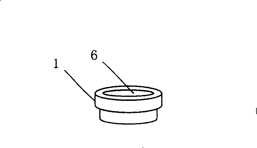
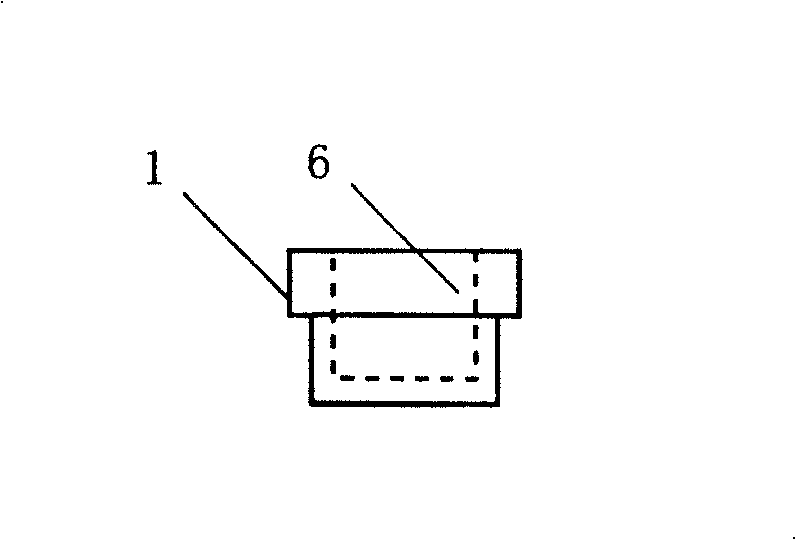
[0017] Such as figure 1 As shown, 1 is a "convex" shaped plug, 2 is a chemiluminescent tube, 3 is a heating device, 4 is a blind hole arranged on the heating device, and 5 is the inner wall of the blind hole 4. in such as figure 1 In the welding method shown, after plugging the opening end of the chemiluminescent tube 2 with the small end of the "convex" shaped plug 1, the blind hole 4 on the heating device 3 is used to fasten the chemical luminescent tube inserted with the plug 1. The end of the luminescent tube 2; the inner end of the blind hole 4 presses the end face of the big end of the plug 1, and the inner wall 5 of the blind hole 4 wraps the outer wall of the end of the luminescent tube 2; the big end of the plug 1 and the area at the end of the chemiluminescent tube 2 begins to melt, after the melting material of the plug 1 and the molten material at the end of the chemiluminescent tube 2 are fused, the heating device 3 is cooled, and the melted material is solidifie...


PUM


Abstract

This invention discloses a sealing chemical luminous tube end method, which comprises the following steps: using a 'U' shape of stifled head to plug the opening end of tube; then using a blind hole heating device to plug the tube end; the blind hole inner end tightly pressing the plug end and the inner wall covers the tube outer side; the most part of the plug and tube are melted to seal the gap between plug and the chemical tube.

Description

technical field [0001] The invention relates to a method for sealing the end of a chemiluminescence tube. Background technique [0002] Chemiluminescence tube is a common independent light-emitting device, which is mainly used in entertainment occasions, such as concert scenes, and can also be used in military fields and first aid occasions. In the past, when the end of the chemiluminescent tube was processed, the material at the opening end of the chemiluminescent tube was directly melted and closed, and then welded. This welding method tends to produce air holes in the center of the welded seal after welding, causing the product to leak, especially This phenomenon is more serious for large diameter chemiluminescent tubes. Another welding sealing method is to insert a cylindrical plug into the cavity of the open end of the chemiluminescent tube, and then weld it by heat sealing. However, during the welding process of this welding method, the plug will move to the inside o...

Claims


Application Information

Patent Timeline
Patent Type & Authority Patents(China)
IPC IPC(8): F21K2/06B29C65/18
Inventor 金朝阳
Owner 金朝阳
Why Eureka
Try Eureka