Multiple changing mode power control method

A technology of power control and control method, which is applied in the direction of electric light source, light source, electrical components, etc., can solve the problems of insufficient lamp voltage, unable to stimulate the load action, unable to light up any more, and achieve the effect of preventing rapid aging

Inactive Publication Date: 2009-01-28
ZIPPY TECH
View PDF4 Cites 0 Cited by
  • Summary
  • Abstract
  • Description
  • Claims
  • Application Information

AI Technical Summary

Problems solved by technology

[0012] The biggest problem with the above method is that when the total modulation energy changes, the maximum excitation energy amplitude height also decreases, and it may be at half the amplitude energy height It will not be possible to stimulate the load action (for example, the lamp voltage is insufficient and cannot be lit anymore, or some electromechanical components cannot be actuated due to insufficient kinetic energy due to peak excitation

Method used


Image

  • Multiple changing mode power control method
  • Multiple changing mode power control method
  • Multiple changing mode power control method

Examples


Embodiment Construction

[0020] Relevant detailed content and technical description of the present invention, now in conjunction with accompanying drawing, explain as follows:

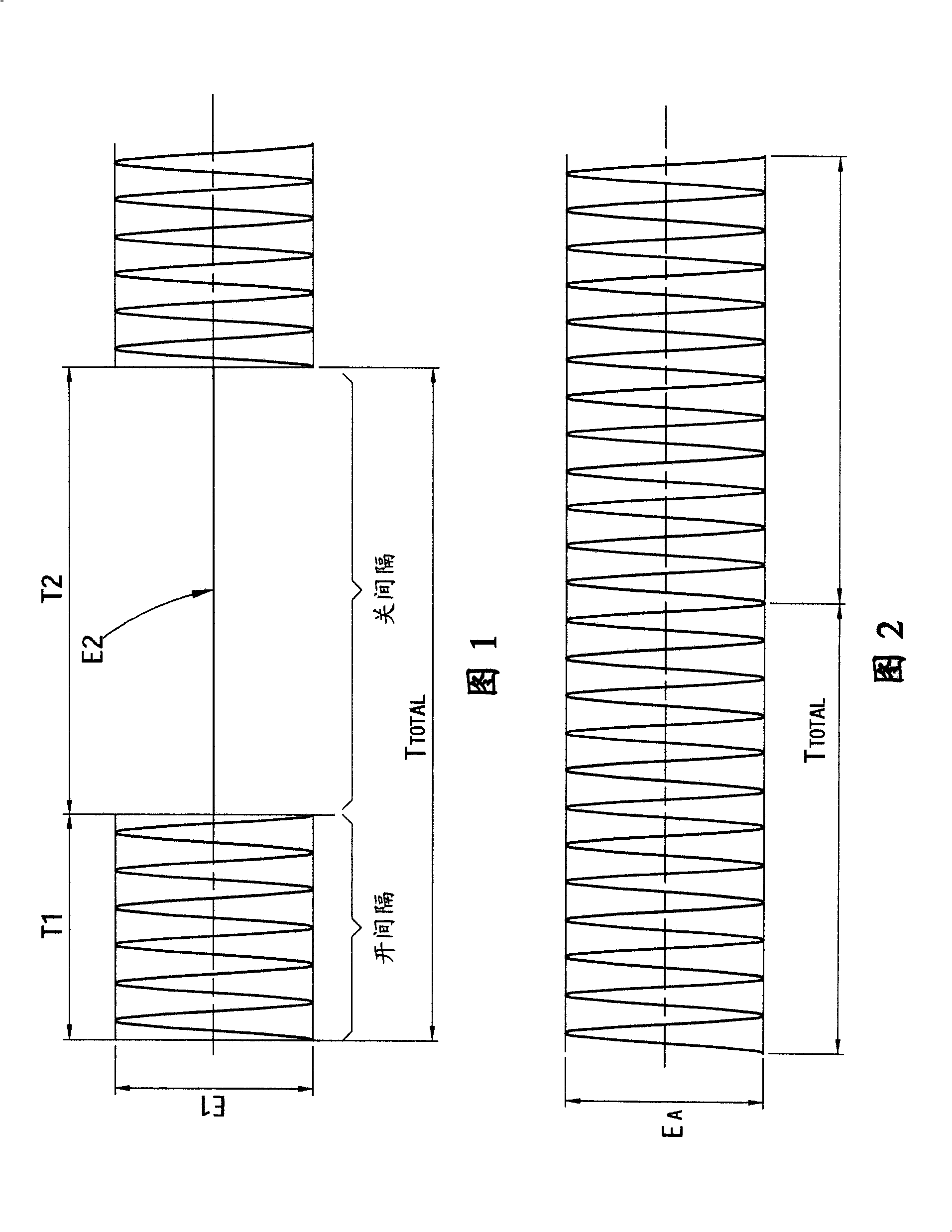
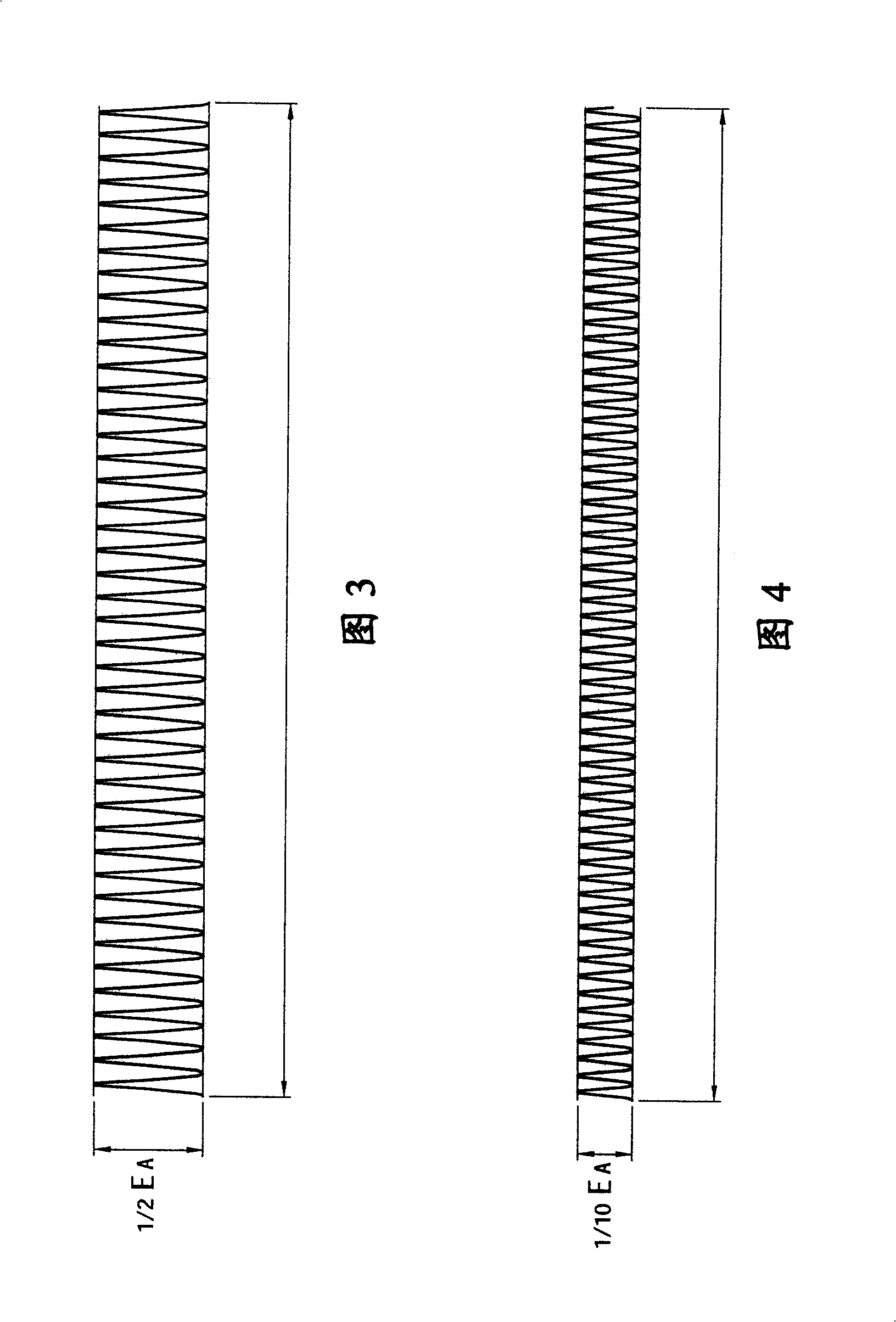
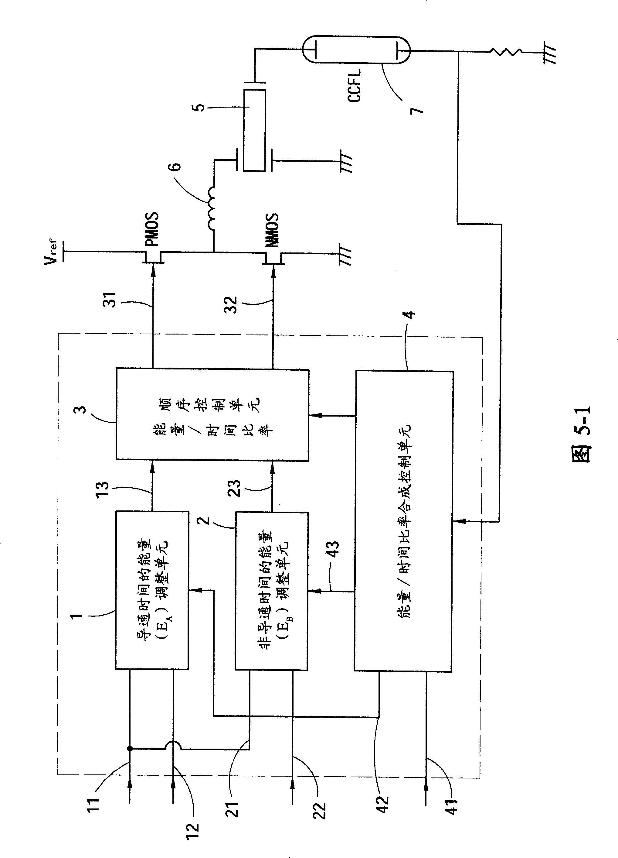
[0021] Please refer to FIG. 5-1 , which is a functional block diagram of a control device implementing the method of the present invention. The power supply control method with multiple modulation modes proposed by the present invention mainly includes the conduction time T A and non-conduction time T B The non-conduction time of the periodic control signal (T B ) to add a modulation energy (E B ), and then get a new incentive dynamic ratio (see Figure 6).

[0022] In order to realize the above-mentioned multi-mode power supply control method of the present invention, the used control device includes: a conduction time energy (E A ) adjustment unit 1, the energy of a non-conduction time (E B ) adjustment unit 2, an energy / time ratio sequence control unit 3, and an energy / time ratio synthesis control unit 4;

[0023] Ener...


PUM


Abstract

This invention discloses a power control method for multiple variable modes, which utilizes the periodic control signals of multiple variable modes to effectively control the energy conversion elements with specific performance to guarantee that said element and its back loading is in the reliable performance sphere and prevents the quick ageing of the loading including: generating periodic control signals including conduction time and non-conduction time and adding control energies of different variables and different frequencies in the above mentioned non-conduction time to provide multiple variable modes mixing the regulated duty ratio, FM / AM to provide a power control method of wide and dynamic sphere.

Description

technical field [0001] The invention relates to a power supply control method, in particular to controlling an energy conversion element through periodic control signals of various modulation modes, thereby providing a power supply control method with high reliability and wide dynamic range. Background technique [0002] The previous power adjustment control (such as dimming control) adopts the on-off interval regulation method of the time cycle, and obtains different output energies by modulating the ratio of the on-off cycle (T1, T2) (as shown in Figure 1 ). The incentive dynamic ratio obtained in this way is defined as follows (Formula 1): [0003] [0004] While the traditional incentive dynamic ratio is E 1 E 2 ≈ 0 ⇒ ∞ , The obtained excitation dynamic ratio is as high as infinity (the implication can ...

Claims


Application Information

Patent Timeline
Patent Type & Authority Patents(China)
IPC IPC(8): H02M1/08H02M7/00H05B41/14
Inventor 周进文郑英男吴光明钟金标
Owner ZIPPY TECH
Why Eureka
Try Eureka