Ion concentration monitor for purifying blood

A blood purification and ion concentration technology, applied in blood circulation processing, instruments, blood filtration, etc., can solve problems such as difficulty in ensuring product consistency and stability, and achieve the effect of ensuring consistency and stability and reducing difficulty requirements

Active Publication Date: 2009-02-11
SWS HEMODIALYSIS CARE CO LTD
View PDF6 Cites 1 Cited by
  • Summary
  • Abstract
  • Description
  • Claims
  • Application Information

AI Technical Summary

Problems solved by technology

[0005] The traditional ion concentration monitoring device for blood purification generally includes a detection control circuit, a conductivity sensor and a temperature sensor installed in the liquid system of the blood purification equipment, wherein the conductivity sensor adopts the electrode direct contact method, that is, the electrode is immersed in the solution For measurement, the temperature sensor is also immersed in the solution for measurement, and the conductivity sensor and temperature sensor respectively transmit signals to the detection control circuit; the traditional detection control circuit often realizes the correction of the measured value of conductivity through a constant temperature environment or through a temperature compensation circuit , since the resistance network cannot make its equivalent temperature characteristics and the temperature characteristics of the conductance sensor completely cancel each other in the entire range, this method of temperature compensation can only truly achieve temperature compensation at a few points
[0006] The disadvantage of the traditional ion concentration monitoring device for blood purification is that the product manufacturing needs to be strictly controlled by the installation process and material process, and it is difficult to ensure the consistency and stability of the product

Method used


Image

  • Ion concentration monitor for purifying blood
  • Ion concentration monitor for purifying blood
  • Ion concentration monitor for purifying blood

Examples


Embodiment Construction

[0059] The present invention will be described in further detail below in conjunction with the accompanying drawings and specific embodiments.

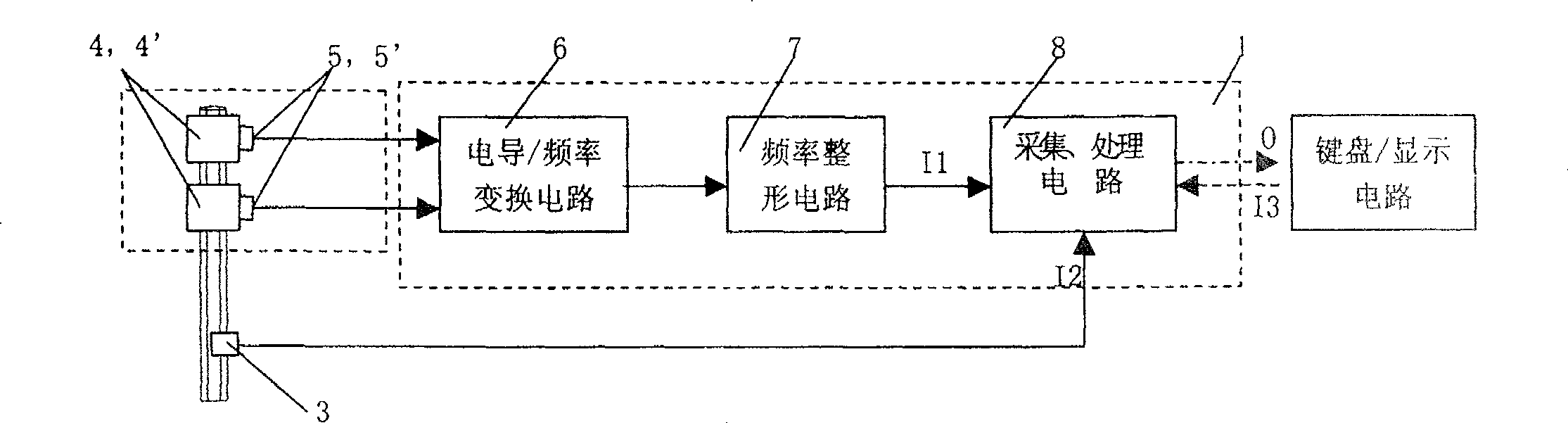
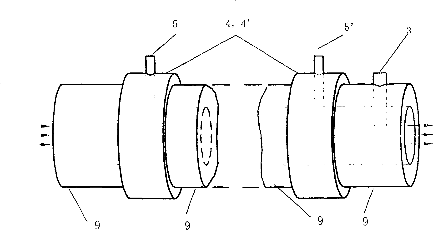
[0060] as attached figure 2 , attached image 3 Shown: an ion concentration monitor for blood purification, including a detection control circuit 1, a conductivity sensor 2 and a temperature sensor 3 installed in the liquid circuit system of the blood purification equipment, wherein the detection control circuit 1 includes an acquisition and processing circuit 8. The temperature sensor 3 is located in the liquid circuit system, the output end of the temperature sensor 3 is connected to the acquisition and processing circuit 8 in the detection control circuit 1, and the acquisition and processing circuit 8 is provided with an alarm signal output end O, where:

[0061] The detection control circuit 1 also includes a conductance / frequency conversion circuit 6 and a frequency signal shaping circuit 7, wherein the input end of the condu...


PUM


Abstract

The present invention relates to an ion concentration monitoring apparatus for purifying blood. It includes detection control circuit, electroconductivity sensor and temperature sensor. The output end of the described temperature sensor is connected with collecting and processing circuit in the described detection control circuit. It is characterized by that the described detection control circuit also includes: the input end of elecroconductivity / frequency conversion circuit is connected with output end of electroconductivity sensor, the output end of said electroconductivity / frequency conversion circuit is connected with frequency signal shaping circuit, the output end of frequency signal shaping circuit is connected with input end of the described collecting and processing circuit. The described electroconductivity sensor is formed from first and second graphite rings and first and second electrodes, the described first and second electrodes are respectively fixed on outer walls of first and second graphite rings, said first and second electrodes are also connected with electroconductivity / frequency conversion circuit conductor.

Description

technical field [0001] The invention belongs to an ion concentration monitor for blood purification, and relates to a monitor for monitoring the safe range of ion concentration in dialysate for blood purification. Background technique [0002] In the blood purification equipment, the patient's blood flows out of the body and returns to the body through the extracorporeal circulation formed by the pipeline. In this circulation system, it mainly includes three parts: blood circuit, fluid circuit and monitoring system. The blood in the patient's body is drawn out of the body, enters the extracorporeal pipelines such as dialyzer or filter, and flows back into the human body to form a blood system; Diffusion, convection, ultrafiltration and other processes, and remove excess water in the patient's body at an appropriate speed. The monitoring system monitors various components, parameters, indicators, etc. of the blood purification equipment, and issues alarms and safety controls...

Claims


Application Information

Patent Timeline
Patent Type & Authority Patents(China)
IPC IPC(8): A61M1/00A61M1/14A61M1/36A61M1/34G01N27/08G01N27/00
Inventor 高光勇王质刚熊建琼李昔华
Owner SWS HEMODIALYSIS CARE CO LTD
Why Eureka
Try Eureka