Film enclosed electric device and collector covering member for the film enclosed electric device

An electric device, film covering technology, applied to the field of collector covering parts, to achieve the effect of suppressing the increase in weight and improving the electrical insulation characteristics

Inactive Publication Date: 2009-02-18
NEC CORP
View PDF4 Cites 0 Cited by
  • Summary
  • Abstract
  • Description
  • Claims
  • Application Information

AI Technical Summary

Problems solved by technology

According to the known phenomenon and principle that lightning discharges rods mounted on planar areas, there is a maximum possibility that the sharp corners of the aluminum layer 311 under the PP layer 310 with the anode collector 303a and cathode collector 303b Shorted by electricity

Method used


Image

  • Film enclosed electric device and collector covering member for the film enclosed electric device
  • Film enclosed electric device and collector covering member for the film enclosed electric device
  • Film enclosed electric device and collector covering member for the film enclosed electric device

Examples


no. 1 example

[0042] In the following, experiments on the embodiments of the present invention are given.

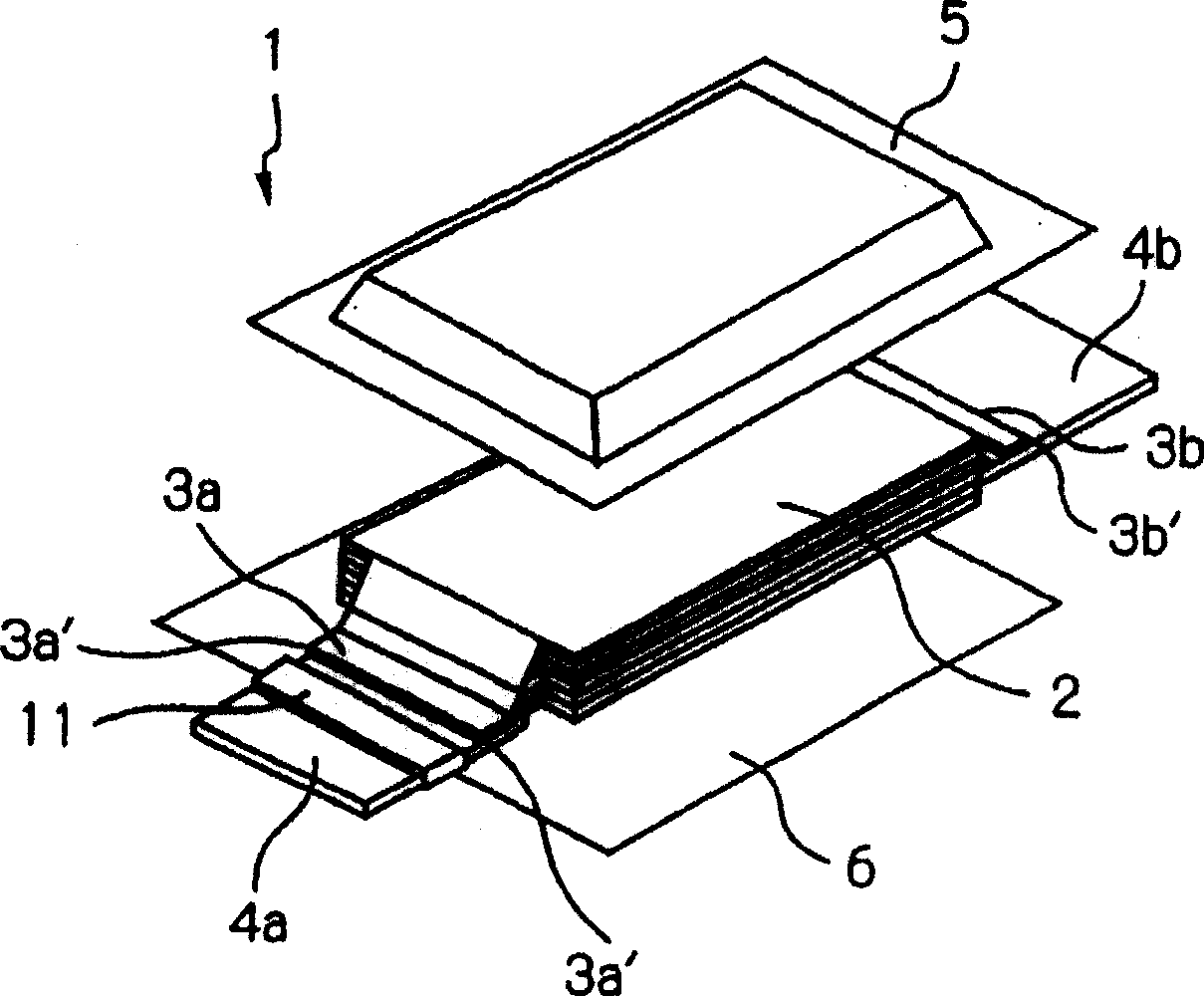
[0043] figure 2 An exploded perspective view of the battery covered by the film is shown. By the way, figure 2 The film covered battery is shown in which the collector protection member according to the first embodiment is removed.

[0044] The thin-film-covered battery 1 has a battery element 2, an anode collector 3a and a cathode collector 3b arranged for the battery element 2, an encapsulation component that houses the battery element 2 and the electrolytic solution together and includes two laminates 5, 6, An anode tab 4a connected to the anode collector 3a, and a cathode tab 4b connected to the cathode collector 3b.

[0045] The battery element 2 is formed by a plurality of anode plates and a plurality of cathode plates alternately stacked via separators.

[0046] Each anode plate is formed by coating an anode electrode on aluminum foil, and a cathode is formed by coating a cathod...

no. 2 example

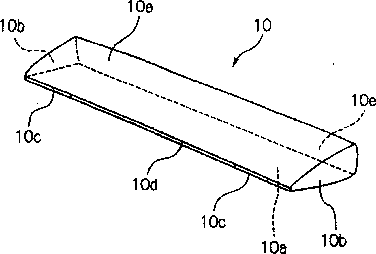
[0073] According to the collector protection member 10 of the first embodiment, the side portion 10b having a three-dimensional shape is formed before bonding and is set in a bag shape in advance, in which the insertion hole 10 and the insertion hole 10e are formed. Such as Picture 9 As shown, the collector protection member 110 according to the present embodiment is formed by bonding two films 112a and 112b together.

[0074] According to the collector protection member 110 of this embodiment, two films 112 are welded only at the side portion 110b and the front portion 110c (by Picture 9 The middle shaded part indicates the welding part 111) and is formed so as to form the insertion hole 110d and the insertion hole 110e. The collector protection member 110 is in a planar shape before being combined.

[0075] Similar to the collector protection member 10 according to the first embodiment, the size of each part is determined so as to achieve the same purpose as the collector prot...

no. 3 example

[0077] The collector protection member 110 according to the second embodiment is formed by bonding two films 112 together. Such as Picture 10 As shown, unlike the second embodiment, the collector protection member 210 according to the present embodiment is made of an inflation film 212.

[0078] According to the collector protection member 210 of this embodiment, the expansion film 212 is bent at the two bent portions 213a, 213b, and the part of the front part 210c is welded (by Picture 9 The middle shaded part indicates the welding part 211) and is formed so as to form the insertion hole 210d and the insertion hole 210e.

[0079] Similar to the collector protection member 10 according to the first embodiment, the size of each part is determined so as to achieve the same purpose as the collector protection member 10 according to the first embodiment. It is preferable to set the welding edge (margin) of the welding portion 211 to be wide so that the current path can be set as lon...


PUM

PropertyMeasurementUnit
thicknessaaaaaaaaaa
thicknessaaaaaaaaaa

Abstract

Corners 3a', 3b' of anode collector 3a and cathode collector 3b are covered with collector protection member 10. Collector protection member 10a is a member in the form of a bag of a resin-made film, and is formed at front surface 10c thereof with insertion hole 10d for allowing anode tab 4a and anode collector 3a or cathode tab 4b and cathode collector 3b to be inserted thereinto. Collector protection member 10 is vacuumed when battery element 2 is sealed with laminate films 5, 6, thereby ensuring tight contact of collector protection member 10 with anode collector 3a and cathode collector 3b.

Description

Technical field [0001] The present application relates to a film-covered electrical device, in which electrical device components represented by batteries and capacitors are contained in a packaging film. In particular, the present invention relates to a collector cover member for covering a collector electrode in an electrical device covered by a film. Background technique [0002] In recent years, there is a strong need to reduce the weight and thickness of batteries used as power sources for mobile phones and the like. Therefore, for materials used to encapsulate batteries, instead of using the metal shell described in the related art (which limits reduction in weight and thickness), thin metal films or laminated films formed by laminating thin metal films, and heat have been used. As the sealing material, the sealing resin film can be further reduced in thickness and weight compared with a metal shell and its shape can be freely deformed. Therefore, for packaging materials fo...

Claims


Application Information

Patent Timeline
Patent Type & Authority Patents(China)
IPC IPC(8): H01M2/02H01G11/00H01G11/10H01G11/12H01G11/66H01G11/74H01G11/76H01G11/78H01G11/82H01G11/84H01M10/04H01M10/052H01M10/36H01M50/55H01M50/557
CPCY02E60/12H01M2/0212H01M10/0436H01M10/052H01M2/06Y02E60/10H01M50/557Y02P70/50H01M50/55
Inventor 水田政智
Owner NEC CORP
Why Eureka
Try Eureka