Experimental device for gas thermal diffusion test in loose coal

An experimental device and thermal diffusion technology, which are applied in the field of experimental devices for testing gas thermal diffusion in loose coal, can solve problems such as insufficient understanding of mutual relationships, safety and health hazards of safety production workers, and little research on the mechanism of action and influencing factors. , to achieve the effect of easy control, improved heat utilization efficiency, and easy promotion and use

Inactive Publication Date: 2017-11-24
XIAN UNIV OF SCI & TECH
View PDF3 Cites 0 Cited by
  • Summary
  • Abstract
  • Description
  • Claims
  • Application Information

AI Technical Summary

Problems solved by technology

In this way, the high temperature point will self-circulate to entrain the surrounding fresh gas, promote the outward development of the high temperature area, and eventually develop into an uncontrollable coal spontaneous combustion fire, which will bring great harm to the safe production of coal mines and the safety and health of workers.
[0003] Existing studies have shown that oxygen supply has a great impact on the development of coal fires, but the current research on oxygen supply power sources is mostly focused on external mechanical air leakage, and self-entrainment oxygen supply caused by high-temperature loose coal due to density differences. There are few studies on the mechanism and influencing factors of the process; however, in the actual process, the self-entrainment and oxygen supply of loose coal is an important influencing factor for the development of the fire zone and the diffusion and migration of gas products.
At present, the range of influence of high-temperature regions on the diffusion and migration of surrounding gases at different temperatures, and the effects of factors such as temperature T, void ratio ε, and high-temperature point orientation θ that affect gas thermal flow and migration, and the relationship between them are not well understood.

Method used


Image

  • Experimental device for gas thermal diffusion test in loose coal
  • Experimental device for gas thermal diffusion test in loose coal
  • Experimental device for gas thermal diffusion test in loose coal

Examples


Embodiment Construction

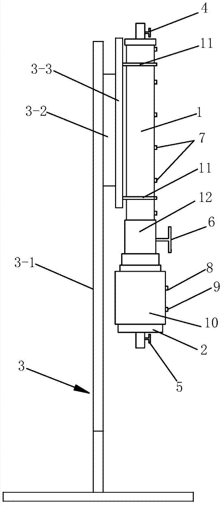
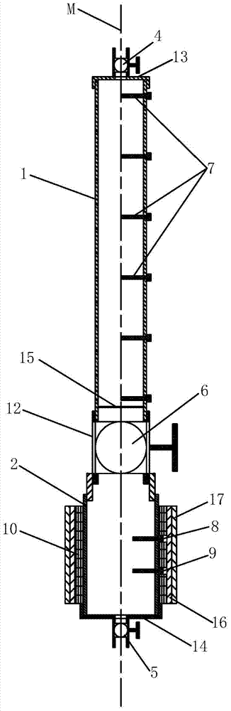
[0036] Such as figure 1 , figure 2 and image 3 The shown experimental device for gas thermal diffusion test in loose coal includes a coal tube 1 for containing loose coal, a gas tube 2 for generating hot air, and a tube 1 for supporting the coal and the support 3 of the gas containing pipe 2, the support 3 is connected with the coal body containing pipe 1; one end of the coal body containing pipe 1 is connected with the end of the gas containing pipe 2 through a variable diameter joint 12, and the coal body containing The other end of the pipe 1 is provided with a first valve 4 for closing or opening its end opening, and the other end of the gas containing pipe 2 is provided with a second valve 5 for closing or opening its end opening. The joint 12 is provided with a third valve 6 for controlling the connection or shut-off of the coal body storage pipe 1 and the gas storage pipe 2. The coal body storage pipe 1 is provided with a partition 15, and the partition 15 is provid...


PUM


Abstract

The invention discloses an experimental device for testing thermal diffusion of gas in a loose coal body, which comprises a coal body containing pipe, a gas containing pipe and a support, the support is connected to the coal body containing pipe; one end of the coal body containing pipe and one end of the gas containing pipe pass through a variable Joint connection, the other end of the coal body containing pipe is provided with the first valve, the other end of the gas containing pipe is provided with the second valve, the third valve is provided in the variable diameter joint, the coal body containing pipe is provided with a partition, and air holes are opened on the partition, and the coal body containing The first air pressure sensor is installed on the pipe, and the second air pressure sensor and temperature sensor are installed on the gas containing pipe. A full pressure sensing hole is provided on the side wall of the tube containing the gas, and an electric heating element is wound around the outer wall of the tube containing the gas. The experimental device has a simple structure and good experimental effect, and can effectively test the gas thermal diffusion effect in the loose coal body.

Description

technical field [0001] The invention belongs to the technical field of thermal diffusion of gas in loose coal, and in particular relates to an experimental device for testing thermal diffusion of gas in loose coal. Background technique [0002] Due to the joint action of various internal and external factors, the loose and broken coal body forms a relatively high-temperature area locally with a temperature higher than that of the surrounding area. The high-temperature area will generate high-temperature gas products and heat the surrounding gas through heat radiation, heat conduction, and heat convection effects. , After the gas is heated, the buoyancy and pressure difference will be generated due to the density change, which will promote the upward migration of the gas, and the surrounding gas will fill the vacancy caused by the gas migration. In this way, the high temperature point will self-circulate to entrain the surrounding fresh gas, promote the outward development of...

Claims


Application Information

Patent Timeline
Patent Type & Authority Patents(China)
IPC IPC(8): G01N25/20
Inventor 翟小伟王凯王伟峰肖旸马砺马腾徐宇葛晖
Owner XIAN UNIV OF SCI & TECH
Why Eureka
Try Eureka