Display unit and scanning method therefor

A technology of display device and scanning direction, which is applied in the direction of scanning details of TV system, image reproducer of projection device, TV, etc. Noise, high-definition image display, anti-enlargement effect

Inactive Publication Date: 2009-03-25
PANASONIC CORP
View PDF6 Cites 0 Cited by
  • Summary
  • Abstract
  • Description
  • Claims
  • Application Information

AI Technical Summary

Problems solved by technology

[0012] That is, regarding the rotation speed of the polygon mirror, under the situation that the face number of the polygon mirror is fixed as 20 faces, the rotation speed (RPM)=1125 (bar)*30 (time)*60 (second)÷20 (face)=approximately 10 Ten thousand (RPM), but in order to achieve such a high-speed rotation, not only must use a high-performance polygon mirror, but also must have a high-performance motor and a high-durability motor bearing. Furthermore, in the case of making it rotate at such a high speed , in addition to the increase in noise during rotation, there is also a problem that the power consumption of the motor also increases
[0013] In addition, it is also conceivable not to increase the rotational speed of the polygon mirror, but to increase the number of scanning lines by increasing the number of faces of the polygon mirror, but in the case of increasing the number of faces of the polygon mirror, the size of the polygon mirror itself becomes larger, resulting in Difficult miniaturization of laser display devices

Method used


Image

  • Display unit and scanning method therefor
  • Display unit and scanning method therefor
  • Display unit and scanning method therefor

Examples


Embodiment Construction

[0097] (Embodiment 1)

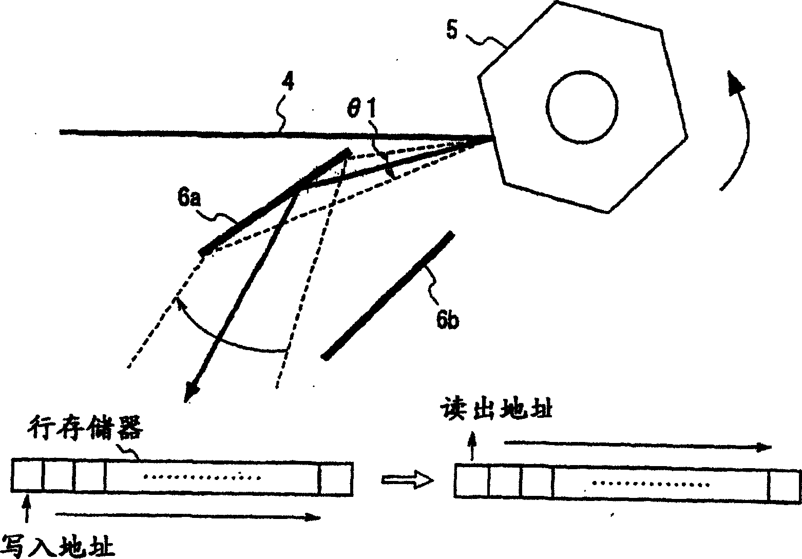
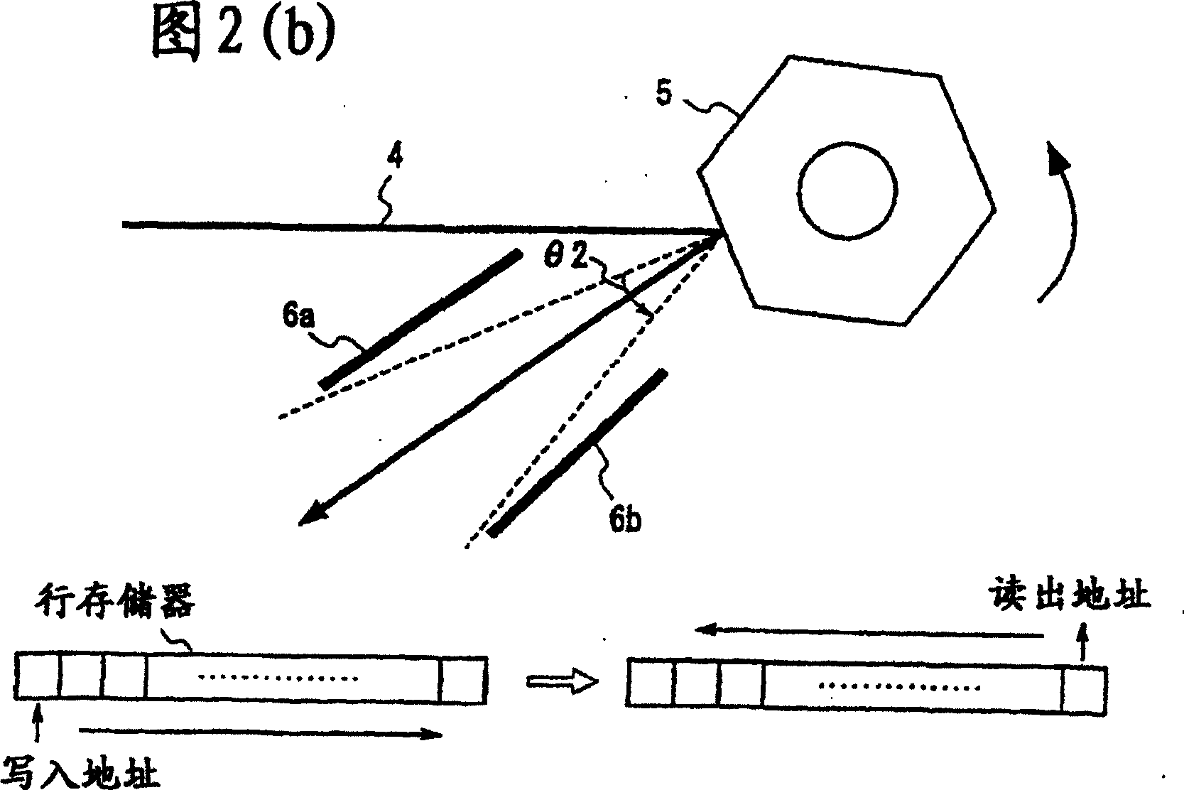
[0098] In the first embodiment, by making the reflected light by the polygon mirror incident on the two mirrors again, a plurality of lines can be scanned on the screen while the laser light is reflected by one side of the polygon mirror.

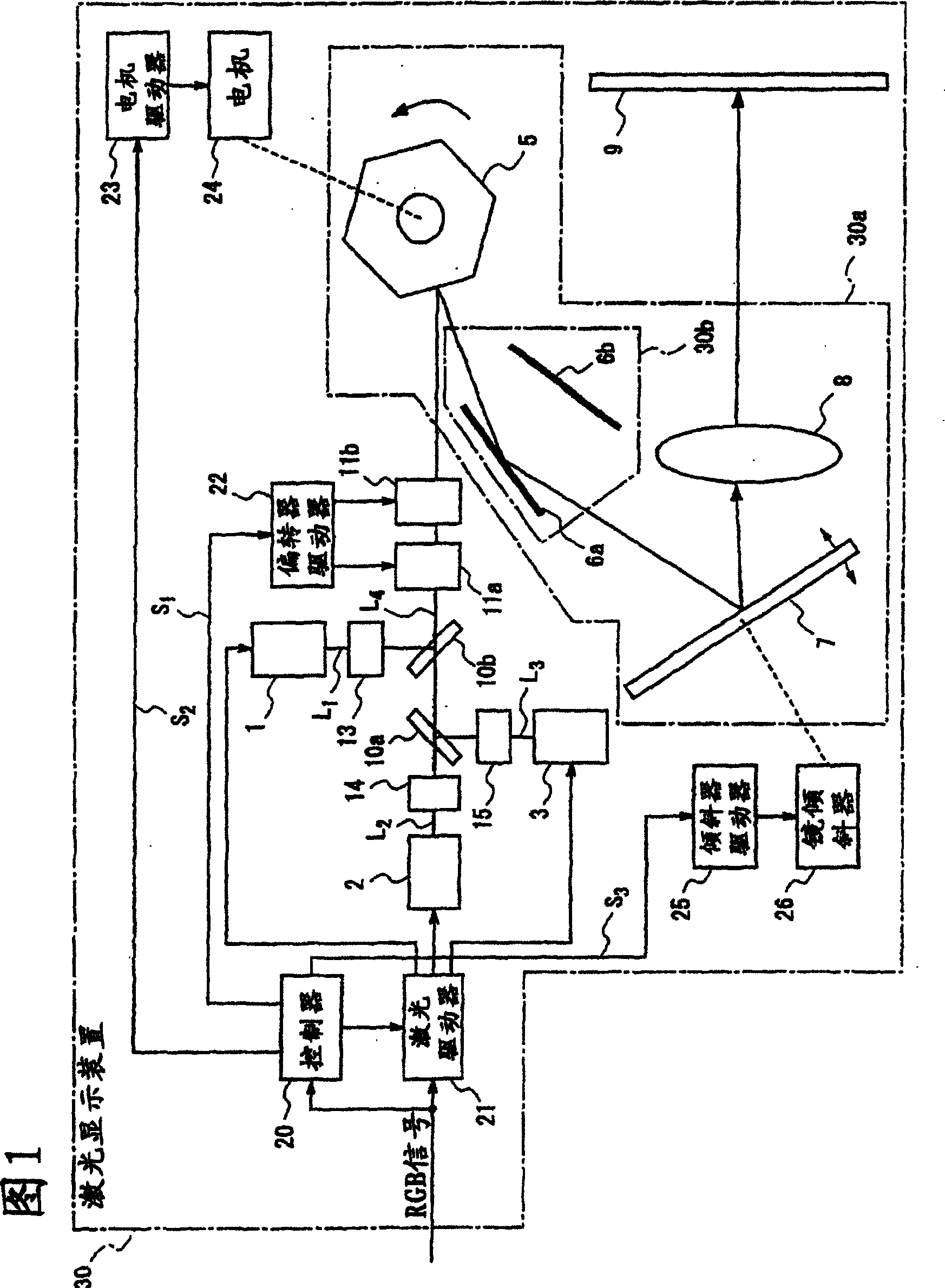
[0099] FIG. 1 is a schematic configuration diagram illustrating a display device according to Embodiment 1 of the present invention.

[0100] The laser display device 30 shown in FIG. 1 has: laser light sources 1 to 3 corresponding to the respective primary color signals RGB of red, green, and blue; The light modulator 13~15 that L3 carries out intensity modulation; The dichroic mirror 10a that synthesizes the laser L2 modulated by the light modulator 14 and the laser L3 modulated by the light modulator 15; The laser L1 modulated by the light modulator 13 and the laser light from a dichroic mirror 10b of the laser light from the dichroic mirror 10a; and high-speed deflectors 11a, 11b that deflect the laser light L4 ...


PUM


Abstract

A display unit, which allows a coherent light to scan on a screen to display an image, is required to rotate a polygon mirror at an ultra-high speed when a high-resolution image is to be displayed such as in the case of HDTV thus requiring the use of a high-performance polygon mirror, and poses noise and power consumption problems when a polygon mirror is rotated. Inserting multi-reflection-use mirrors (6a), (6b) in a coherent-light scanning optical system can provide a plurality of scanning lines while one plane of a polygon mirror (5) scans a coherent light as many as one line to thereby lower the rotation speed of the polygon mirror.

Description

technical field [0001] The present invention relates to a display device and scanning method for projecting coherent light onto a screen or through the screen to project images. Background technique [0002] As a conventional display device using coherent light, for example, a display device using a spatial modulation element such as the display device described in Patent Document 1 is known. Furthermore, in addition to the display device described in the above-mentioned Patent Document 1, as shown in FIG. 7( a ), there is a display device that projects coherent light onto a screen using a polygon mirror. A conventional laser display device shown in FIG. 7(a) will be described below. [0003] FIG. 7(a) is a diagram showing a schematic configuration of a conventional laser display device. [0004] This laser display device 100 includes laser light sources 101a to 101c corresponding to the three colors of RGB and light modulators 106a to 106c for intensity-modulating laser b...

Claims


Application Information

Patent Timeline
Patent Type & Authority Patents(China)
IPC IPC(8): G02B26/10H04N3/08G02B26/12H04N9/31
CPCH04N3/08G02B26/123H04N9/3129G02B26/125Y10S359/90G02B26/10
Inventor 横山敏史笠澄研一森川显洋水内公典山本和久
Owner PANASONIC CORP
Why Eureka
Try Eureka