Assembly type nozzle diaphragm, and method of assembling the same

A technology of nozzle baffles and baffles, which is applied in engine manufacturing, machine/engine, stator, etc., can solve problems such as difficult cost reduction, welding cost reduction, and difficult automatic welding, so as to achieve high turbine classification efficiency and reduce the cost of replacement operations Effect

Inactive Publication Date: 2009-04-01
KK TOSHIBA
View PDF8 Cites 0 Cited by
  • Summary
  • Abstract
  • Description
  • Claims
  • Application Information

AI Technical Summary

Problems solved by technology

However, this method also inherently has its limitations
[0014] (2) About cost: Since there are many welding steps, it is difficult to achieve cost reduction
Therefore, even if the material cost and processing cost are effectively reduced, there is a limit to the cost reduction
In addition, since it is difficult to achieve 100% mechanized and automated welding, it is difficult to reduce the welding cost itself

Method used


Image

  • Assembly type nozzle diaphragm, and method of assembling the same
  • Assembly type nozzle diaphragm, and method of assembling the same
  • Assembly type nozzle diaphragm, and method of assembling the same

Examples


Embodiment Construction

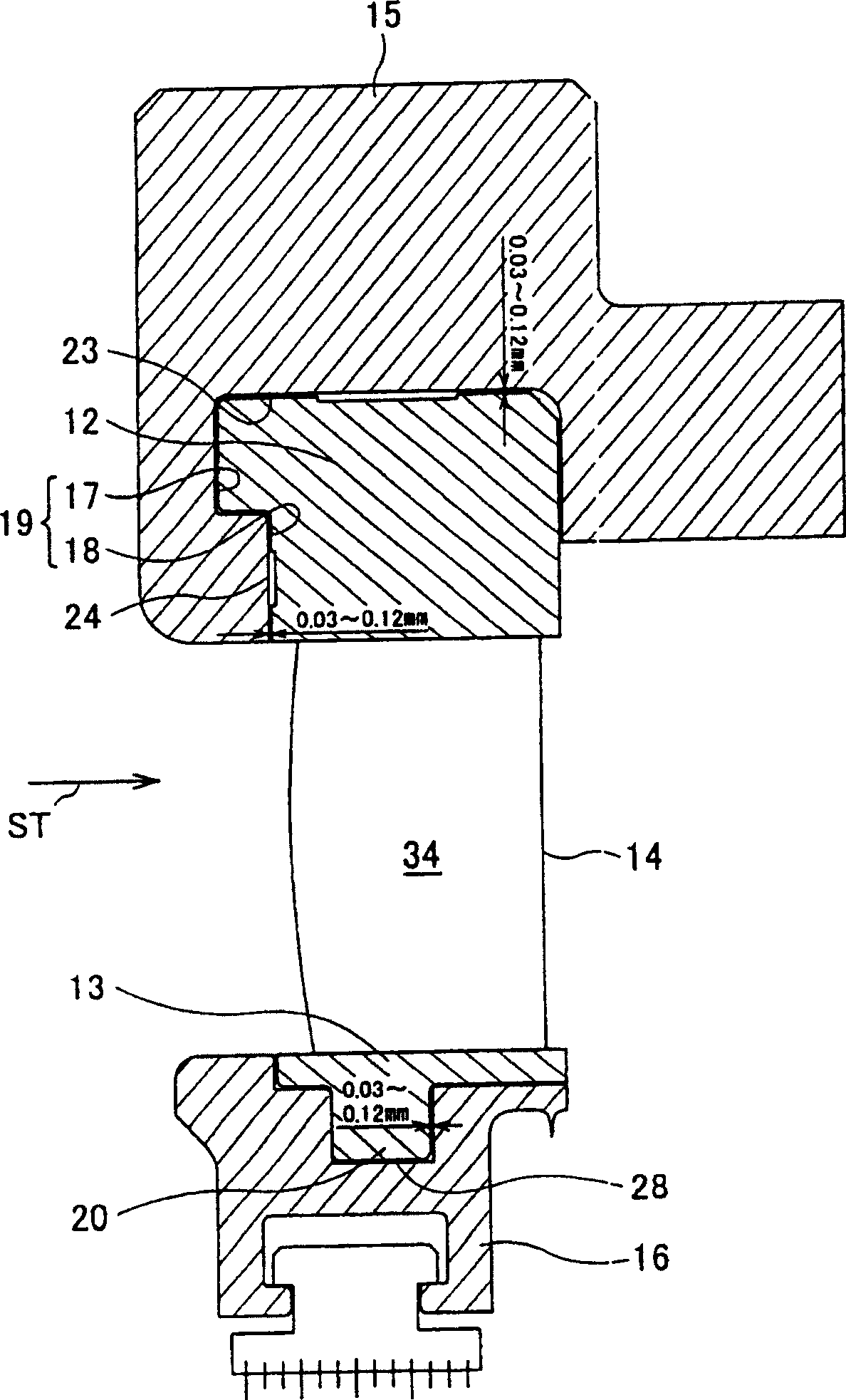
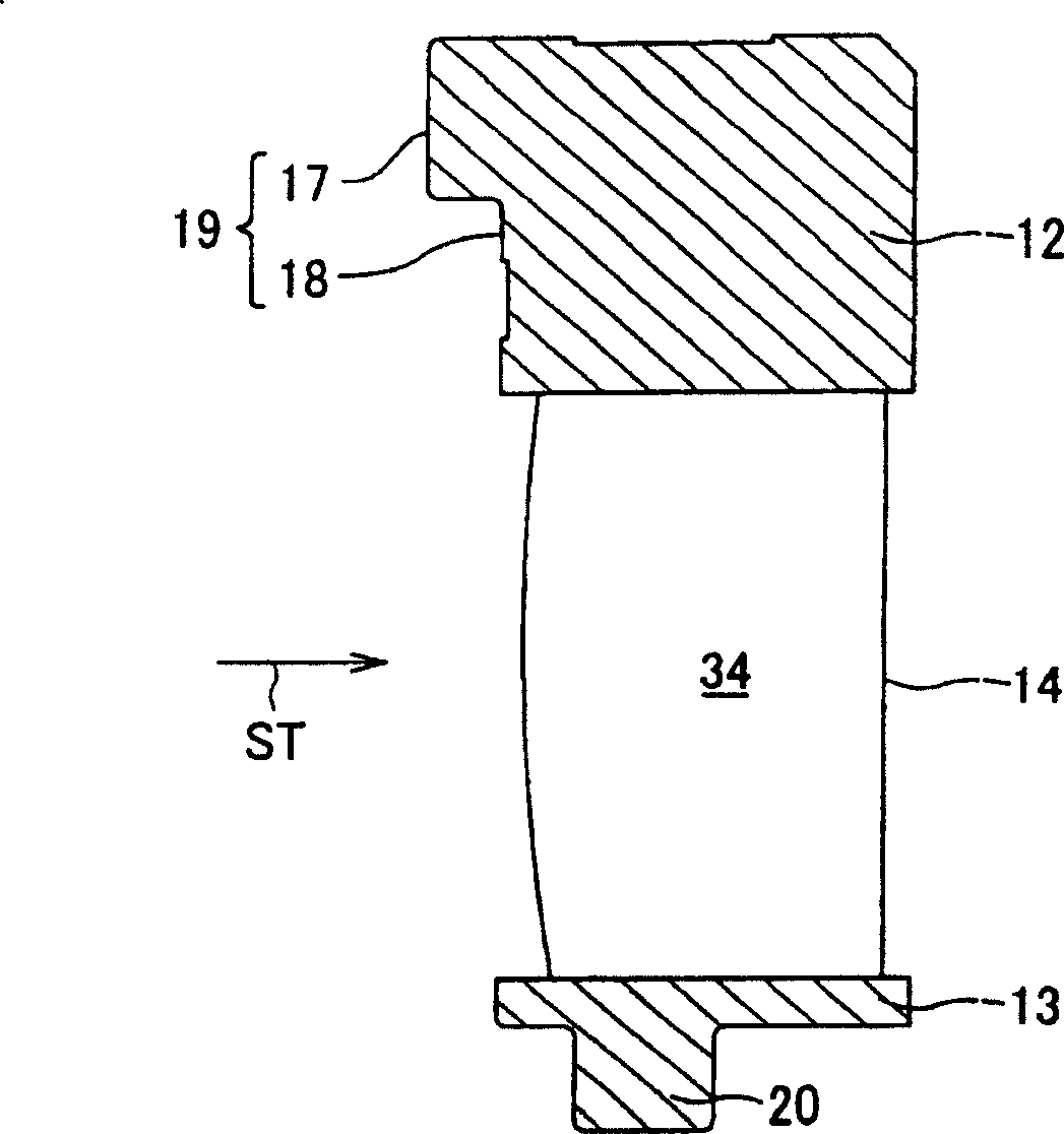
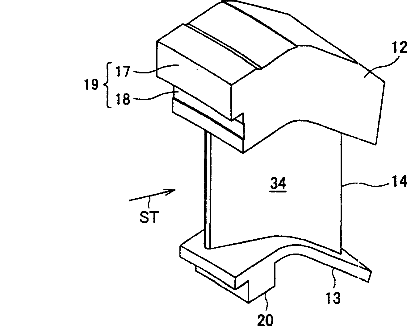
[0075] Embodiments of the assembly type nozzle diaphragm and assembly method of the present invention will be described below by reference numerals attached to the drawings and with reference to the drawings. In various embodiments, fabricated nozzle diaphragms are employed in steam turbines. The reference ST in the figure represents the steam flow inside the steam turbine.

[0076] Figure 31 shows multiple stages of an axial flow steam turbine 100 with fabricated nozzle baffles. Each nozzle vane 104 is connected to the diaphragm outer ring 102 and the diaphragm inner ring 103 , wherein the diaphragm outer ring 102 is connected to the turbine casing 101 , thereby forming nozzle vane flow passages. A plurality of turbine moving (rotor) vanes 106 are arranged downstream of the nozzle vane flow path. The moving blades 106 are built or fitted on the outer periphery of the rotor wheel 105 at predetermined intervals in the circumferential direction, and a cover 107 for preventing ...


PUM


Abstract

An assembled nozzle diaphragm comprises a diaphragm outer ring (15) having a groove opened toward an inner diameter side to be continuous in an inner peripheral direction of the diaphragm outer ring; and a nozzle blade (14) having an insertion portion (12) for the diaphragm outer ring provided on one end, and an inner periphery-side member (48) formed integrally with the nozzle blade on the other end.

Description

technical field [0001] The invention relates to an assembled nozzle diaphragm applied to a steam turbine and a method for assembling the nozzle diaphragm. Background technique [0002] Typically so-called axial flow steam turbines are used, having high power and comprising multiple stages arranged along the direction of steam flow, each stage comprising turbine nozzles (turbine stationary (stator) blades) and turbine moving or moveable (rotor) blades The combination. [0003] The axial flow steam turbine is roughly classified into a reaction type and a push type. [0004] The push type steam turbine utilizes each turbine nozzle to cause steam thermal energy to do more expansion work, uses each turbine moving blade after the expansion work to convert the steam into a deflected flow, and guides the resulting deflected flow to the next stage. [0005] In turbine nozzles, which convert most of the thermal energy of the steam into kinetic energy, a large pressure difference occ...

Claims


Application Information

Patent Timeline
Patent Type & Authority Patents(China)
IPC IPC(8): F01D9/02F01D9/04F01D25/24
CPCF01D9/042F05D2230/61F01D25/246F05B2240/10F05B2230/601F05D2240/10Y10T29/49323F01D9/02
Inventor 佐佐木隆仲摩裕司今井健一
Owner KK TOSHIBA
Why Eureka
Try Eureka