In-tank fuel purifying treatment apparatus

A purification treatment and internal fuel technology, which is applied to fuel injection devices, liquid fuel feeders, internal combustion piston engines, etc., can solve the problems of inability to carry out fuel, troublesome and troublesome, supply or replenishment, etc., and achieve the effect of improving cleanliness

Inactive Publication Date: 2009-04-08
KOMATSU LTD
View PDF3 Cites 0 Cited by
  • Summary
  • Abstract
  • Description
  • Claims
  • Application Information

AI Technical Summary

Problems solved by technology

[0006] Therefore, it is also considered to use the above-mentioned removal device to remove foreign matter in the storage tank, but in an environment where there is a high possibility of frequent contamination of foreign matter, this removal operation is troublesome and time-consuming, and at the same time it is necessary to temporarily empty the fuel storage tank. Fuel supply or replenishment cannot be performed, and there are many problems in implementation
[0007] In addition, since large-scale purification treatment devices for ships cannot be easily installed on construction sites, let alone on the side of construction machinery

Method used


Image

  • In-tank fuel purifying treatment apparatus
  • In-tank fuel purifying treatment apparatus
  • In-tank fuel purifying treatment apparatus

Examples


no. 1 Embodiment approach

[0036] Hereinafter, a first embodiment of the present invention will be described with reference to the drawings.

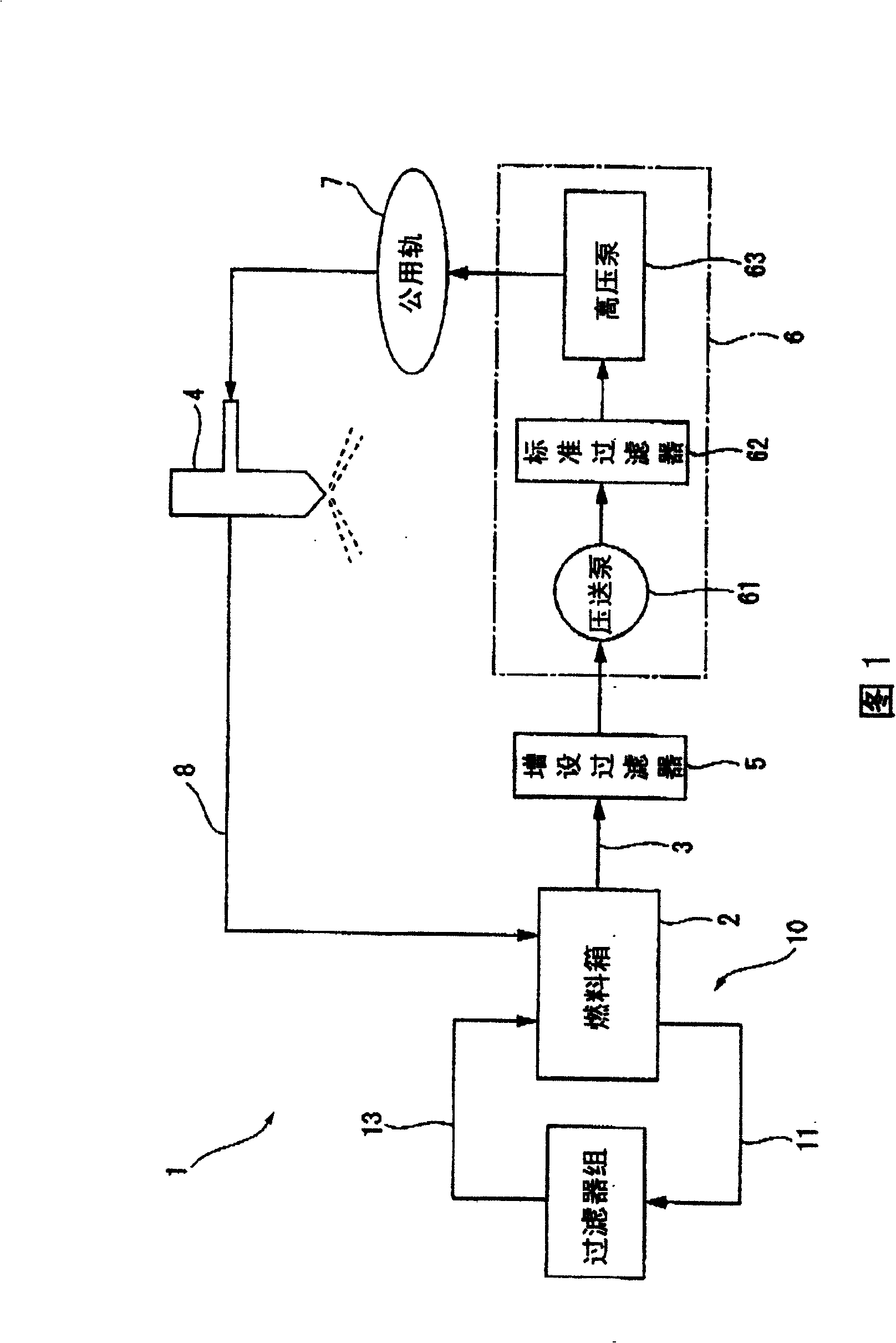
[0037] FIG. 1 is a schematic diagram showing the configuration of main parts of a construction machine 1 such as a hydraulic excavator, a wheel loader, a bulldozer, and a motor grader to which an in-tank fuel purification treatment device 10 according to the present embodiment is applied.

[0038] First, in this construction machine 1, the fuel stored in the fuel tank 2 is supplied to the fuel injection device 4 through the supply path 3, and then injected into the cylinder of the engine (not shown), as in the general specifications. In the supply path 3, an extension filter 5, a fuel pump 6, and a common rail 7 are provided in this order from the upstream side. In addition, the fuel pump 6 includes a pressure feed pump 61 that draws fuel from the fuel tank 2, a standard filter 62 that purifies the fuel discharged from the pressure feed pump 61, and a high pressure...

no. 2 Embodiment approach

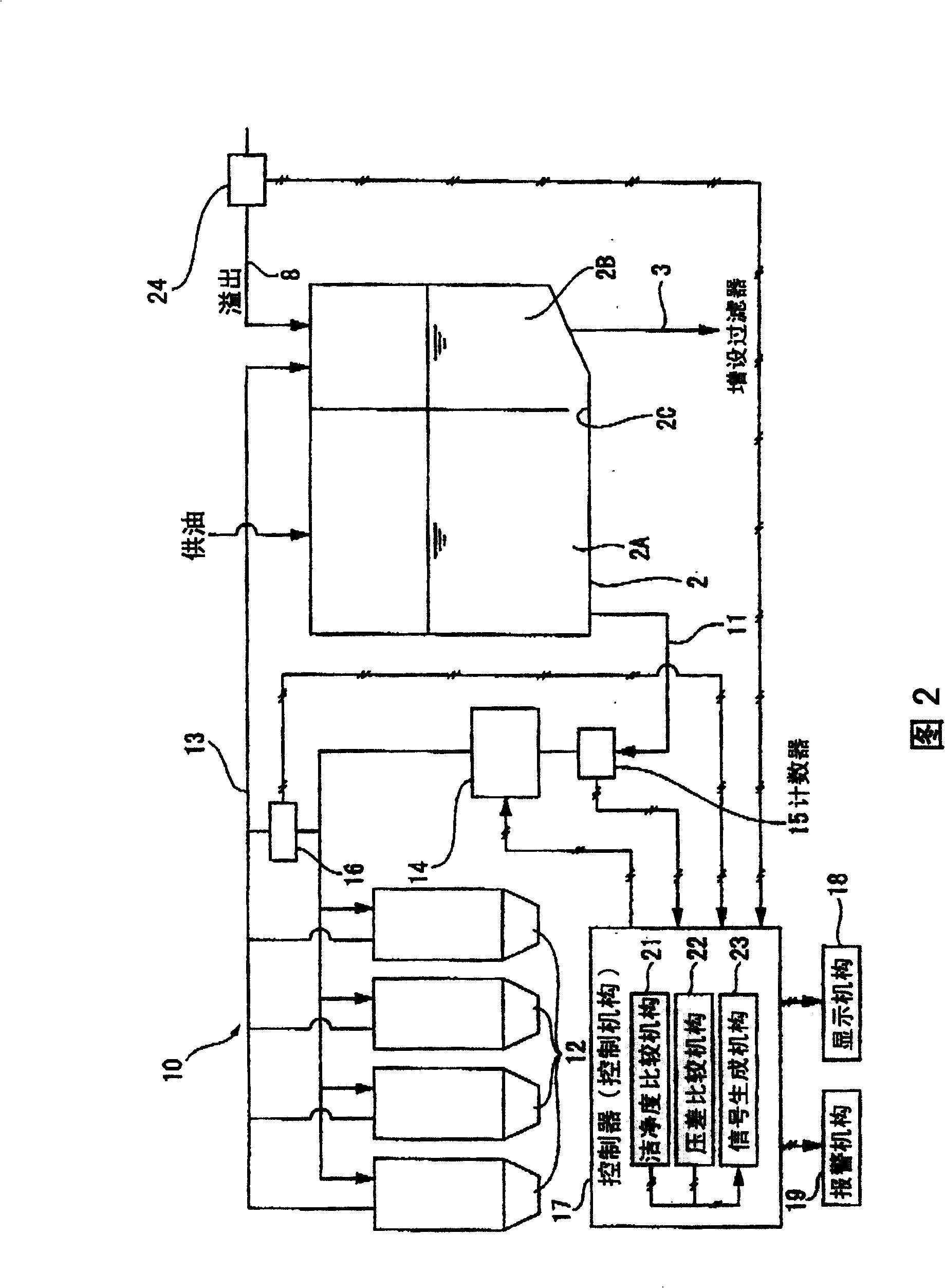
[0078] FIG. 4 is a schematic diagram showing the configuration of main parts of an in-tank fuel purification treatment device 10 according to a second embodiment of the present invention.

[0079] In the above-mentioned first embodiment, the fuel tank 2 is divided into the first container portion 2A and the second container portion 2B, but in this embodiment, the sub-tank 30 is provided on the lower side of the normal fuel tank 2 . The supply path 3 is connected to the sub tank 30 .

[0080] In addition, by providing a switching valve 31 on the fuel delivery path 11 connected to the fuel tank 2, switching operation is performed according to a switching signal from the controller 17, and switching is made between the fuel flow to the particle counter 15 ( FIG. 2 ) side and the secondary fuel flow. Case 30 side flow.

[0081] In addition, the flow of fuel from the fuel tank 2 to the sub-tank 30 is not performed by a pump or the like, but the natural drop of the head pressure is...


PUM


Abstract

The invention provides a tank fuel purifier. A construction machine 1 is provided with the tank fuel purifier 10, whereby the fuel in the fuel tank 2 can be circulated, and filtered by a filter 1 to be automatically purified. Therefore, it is not necessary to once empty the fuel storing tank installed in a job site and eliminate foreign matter staying in the interior of the tank. Further, since purification is automated, the cleanliness of fuel can be easily improved in a short time without trouble. Furthermore, the purifier 10 is composed of a particle counter 15, an oil feed pump 14, a filter 12 and a differential pressure sensor 16, which are components not requiring large space, whereby the purifier 10 can be made enough compact and surely installed without any increase in size of the construction machine 1 itself.

Description

technical field [0001] The present invention relates to an in-tank fuel purification treatment device (hereinafter, sometimes referred to as "treatment device"). Background technique [0002] Conventionally, fuel supplied to construction machinery, etc. used at a construction site is delivered to the site by a fuel tanker from a fuel supplier, temporarily stored in a fuel storage tank installed on the site, and then supplied from the storage tank as needed To the fuel tank of construction machinery. In such fuel storage tanks, it is desired to thoroughly remove rust and the like generated inside, and for this reason, various types of such removing devices and removing agents have been developed. [0003] In addition, in large ships such as oil tankers, although large tanks constituting a part of the hull are installed, during long-term voyages, there is a high possibility of rust or foreign matter being mixed in the tanks, so a large purification treatment device is general...

Claims


Application Information

Patent Timeline
Patent Type & Authority Patents(China)
IPC IPC(8): F02M37/22B01D35/02B60K15/03B01D35/143F02D45/00F02M37/00F02M55/00
CPCY02T10/123Y02T10/12
Inventor 小泽吾道早川荣治
Owner KOMATSU LTD
Why Eureka
Try Eureka