

Drainage valve
A valve and valve body technology, applied in the field of sewer valves, can solve the problems of frequent manual water plug operations, poor water flow, inconvenient use, etc., and achieve the effect of simple structure, low cost, and good sealing effect
- Summary
- Abstract
- Description
- Claims
- Application Information
AI Technical Summary
Problems solved by technology
Method used
Image


Examples
Embodiment 1
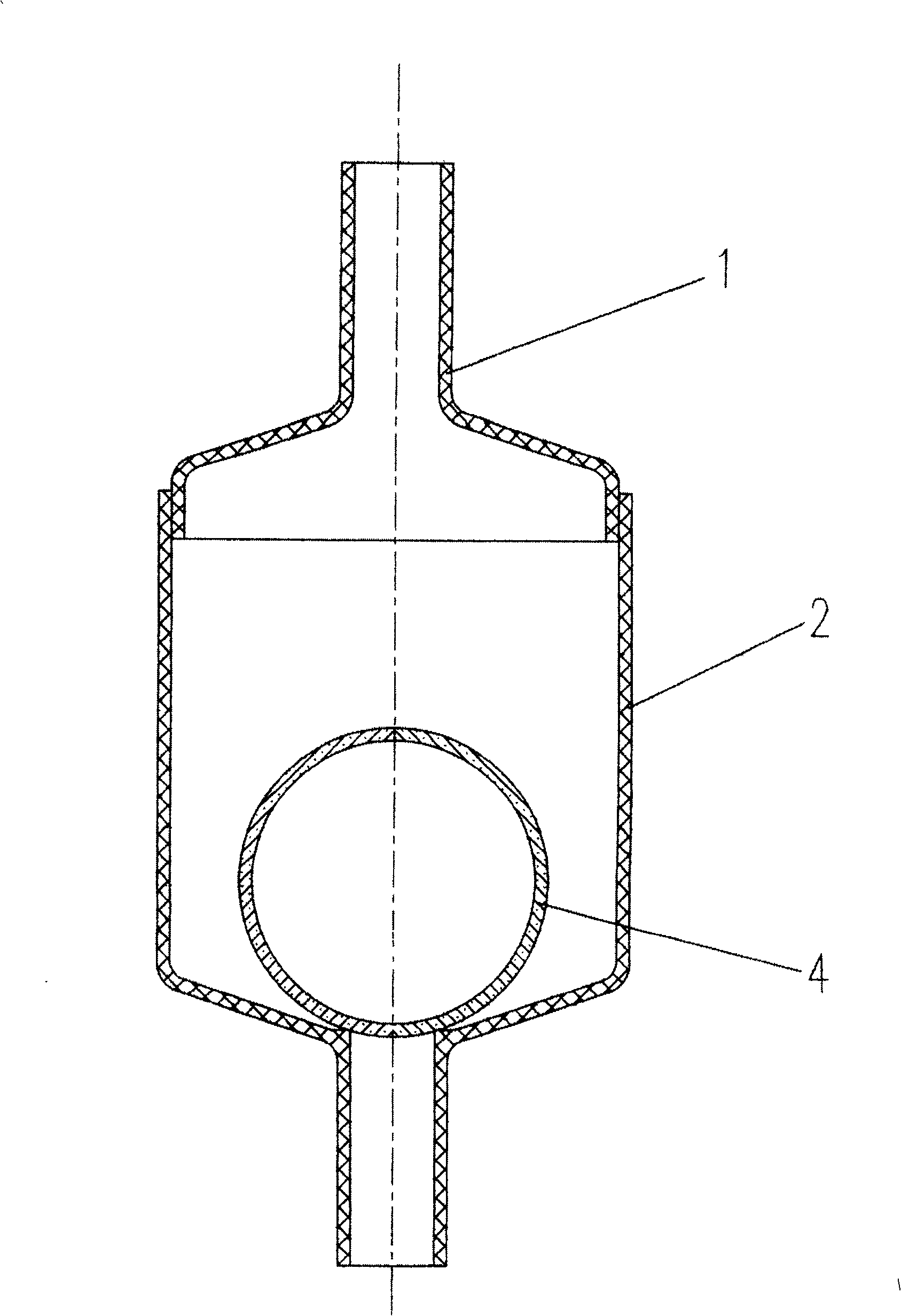
[0023] This embodiment is suitable for being installed under the pool and is similar to the current water return bay type water valve, such as figure 1 As shown, the present invention is a water valve, which is composed of a valve body 8 and a floating valve core 4 arranged in the valve body 8, the valve body 8 is a thick cavity structure in the middle, and the two ends of the cavity are respectively used The water inlet and outlet connected to the drainage pipe network are connected with the cavity in the middle of the valve body; the floating valve core 4 is set in the middle cavity of the valve body 8, which is made of light material A sphere, a hollow sphere, an elliptical sphere or an elliptical hollow sphere can also be a hollow body made of a material with a larger specific gravity, but it must be ensured that the specific gravity of the entire ball is between 0.1 and 0.8, and the outer surface of the floating valve core 4 is in contact with the valve body cavity. The w...
Embodiment 2
[0025] This embodiment is also suitable for being installed under the pool and is similar to the current backwater inlet valve, such as figure 2 As shown, the valve body 8 is fixedly connected by the upper valve body 1 and the lower valve body 2 through threaded engagement, the upper end of the upper valve body 1 is provided with a water inlet, the lower end of the lower valve body 2 is provided with a water outlet, and the water inlet and outlet The nozzle is connected with the upper and lower valve bodies 1 and 2 to form a valve body cavity that is connected internally. Such a structure is convenient for the valve core to be installed in the valve body during the assembly process, and is also convenient for replacing the internal floating valve core 4. The rest of the structure is the same as the embodiment 1.
Embodiment 3
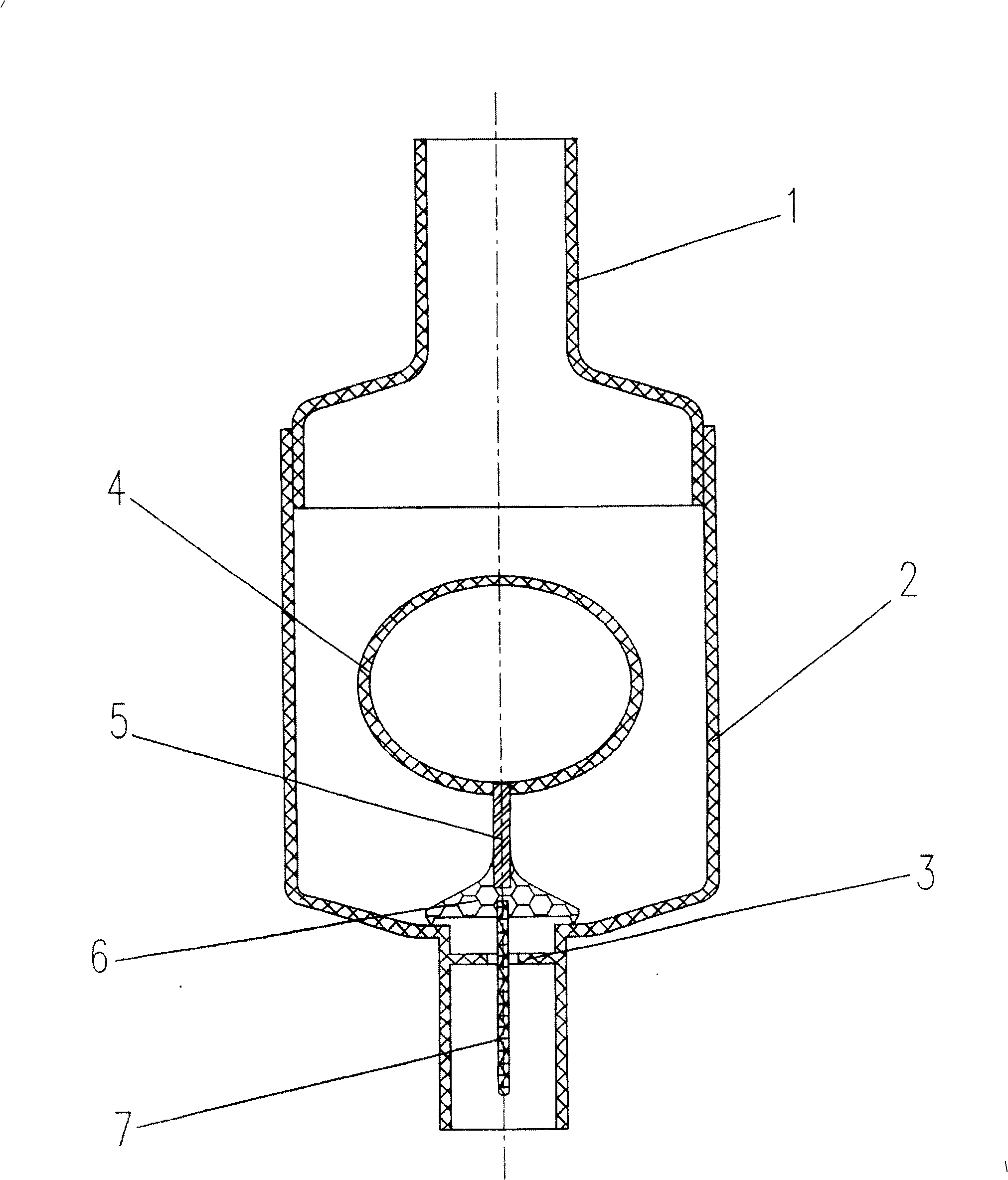
[0027] Such as image 3 As shown, the floating spool 4 is connected with the valve plug 6 which closes the water outlet in the valve body cavity through the connecting rod 5, and the valve plug 6 is provided with a positioning rod 7; the water outlet at the water outlet in the valve body cavity is provided with a positioning pin 3 , There is a circular hole in the center of positioning pin 3, and positioning rod 7 is movable to be arranged in the circular hole of positioning pin 3 and can move up and down. All the other structures are with embodiment 2.
[0028] When there is water flowing into the valve cavity, the floating valve core 4 will generate upward buoyancy, driving the connecting rod 5, valve plug 6, and positioning rod 7 to move upward, so that the valve plug 6 leaves the water outlet in the lower valve body 2, and the lower valve body 2 The water flows down, and after the lower water flows, the floating spool 4 falls automatically under the action of its own grav...
PUM
 Abstract
Description
Claims
Application Information