Dimple forming device
A generator and dimple technology, applied in kneading and massage equipment, medical science, physical therapy, etc., to achieve the effect of convenience, comfort and high safety
- Summary
- Abstract
- Description
- Claims
- Application Information
AI Technical Summary
Problems solved by technology
Method used
Image
Examples
Embodiment 1
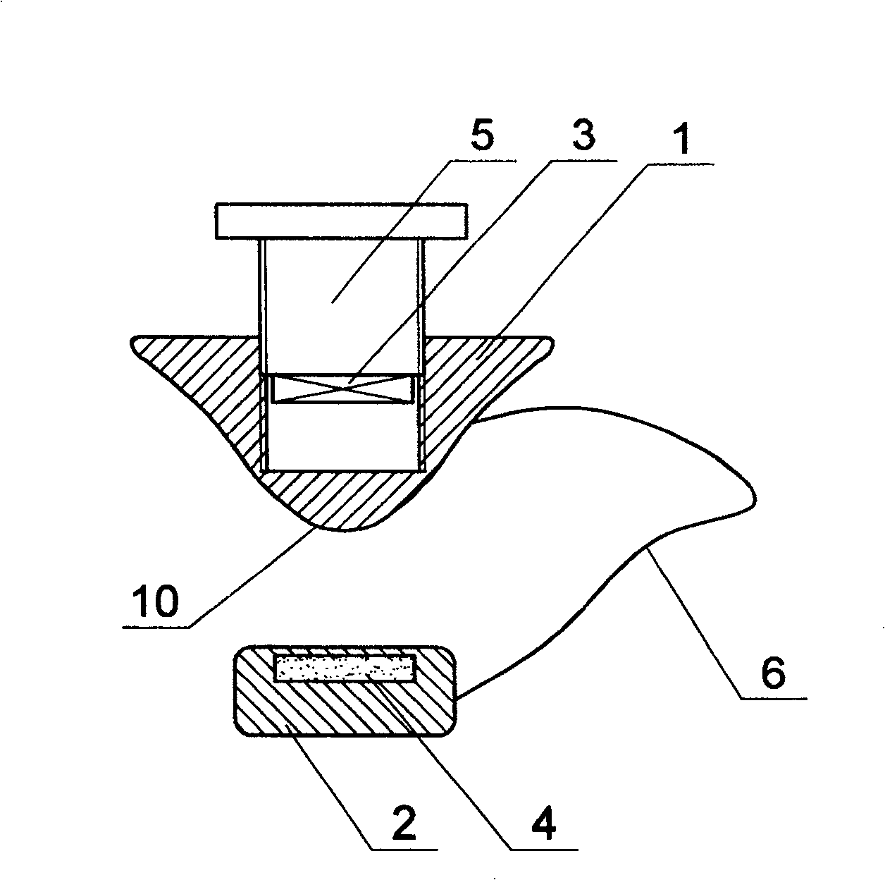
[0024] Such as figure 1 As shown, the present invention comprises molding die 1, liner 2, adjusting bolt 5, connecting wire 6, and described molding die 1, described pad 2 are respectively provided with I magnet 3, II magnet 4, and described molding die 1 The bottom surface has a molding arc surface 10, the molding arc surface 10 is placed on the cheek, the liner 2 is placed in the oral cavity close to the cheek relative to the molding arc surface 10, the I magnet 3, the II magnet 4 phase matching, the forming die 1 is provided with a threaded blind hole, the I magnet 3 is fixedly connected with the bottom of the adjusting bolt 5, and the adjusting bolt 5 is threaded along the axis in the blind hole. The two ends of the connection line 6 are fixedly connected to the molding die 1 and the pad 2 respectively, the I magnet 3 and the II magnet 4 are permanent magnets, and of course electromagnets can also be used. Or use other materials with suction, the pad 2 is sheet-shaped, an...
Embodiment 2
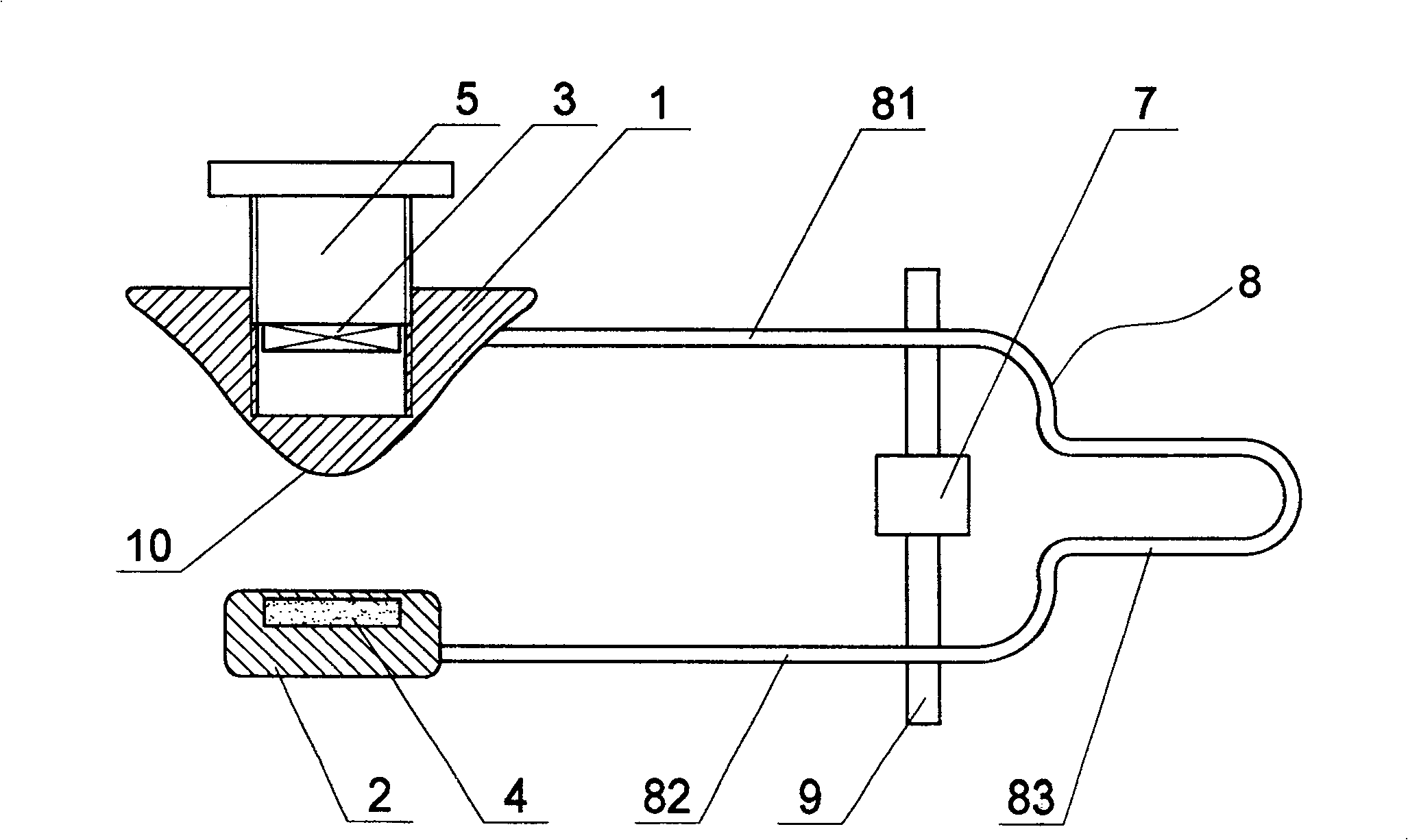
[0026] Such as figure 2 As shown, the difference between this embodiment and Embodiment 1 is that this embodiment does not have a connecting line 6, but also includes an adjusting clip 8 and an adjusting screw 9, and the adjusting clip 8 includes two connecting parts 81, 82, a detour part 83, the front ends of the two connecting parts 81, 82 are respectively connected with the molding die 1 and the pad 2, and the connection method is detachable plug-in, so as to facilitate the removal of the adjustment clip 8, The tail ends of the two connecting parts 81, 82 are connected through the detour part 83, and the detour part 83 is used not only as the handle of the adjusting clip 8 but also as a hook when placed. The threads of the head rotate in opposite directions and are respectively connected to the two connecting parts 81 and 82 via threads. The middle part of the adjusting screw 9 is provided with a handle 7 for conveniently turning the adjusting screw 9 .
[0027] In the pr...
PUM
 Abstract
Description
Claims
Application Information
 - R&D
- Intellectual Property
- Life Sciences
- Materials
- Tech Scout
- Unparalleled Data Quality
- Higher Quality Content
- 60% Fewer Hallucinations
Browse by: Latest US Patents, China's latest patents, Technical Efficacy Thesaurus, Application Domain, Technology Topic, Popular Technical Reports.
© 2025 PatSnap. All rights reserved.Legal|Privacy policy|Modern Slavery Act Transparency Statement|Sitemap|About US| Contact US: help@patsnap.com


