
Secondary optical lens

A secondary optical lens and light-emitting surface technology, applied in the field of LED lighting, can solve the problems of difficult control of the shape of the light spot and low light output rate of secondary optical processing, so as to reduce the loss of secondary refraction, reduce the loss of stray light, and easily The effect of control

Active Publication Date: 2009-05-13
KINGSUN OPTOELECTRONIC CO LTD
View PDF4 Cites 0 Cited by
  • Summary
  • Abstract
  • Description
  • Claims
  • Application Information

AI Technical Summary

Problems solved by technology

This method is used for secondary treatment, because a distance must be preset between the LED bulb and the secondary lens, and the light entering the secondary lens is already stray light, so the light output rate of the secondary optical treatment is low
On the other hand, the light entering the secondary lens is already stray light, and the shape of the light spot is difficult to control

Method used


Image

  • Secondary optical lens
  • Secondary optical lens
  • Secondary optical lens

Examples


Embodiment Construction

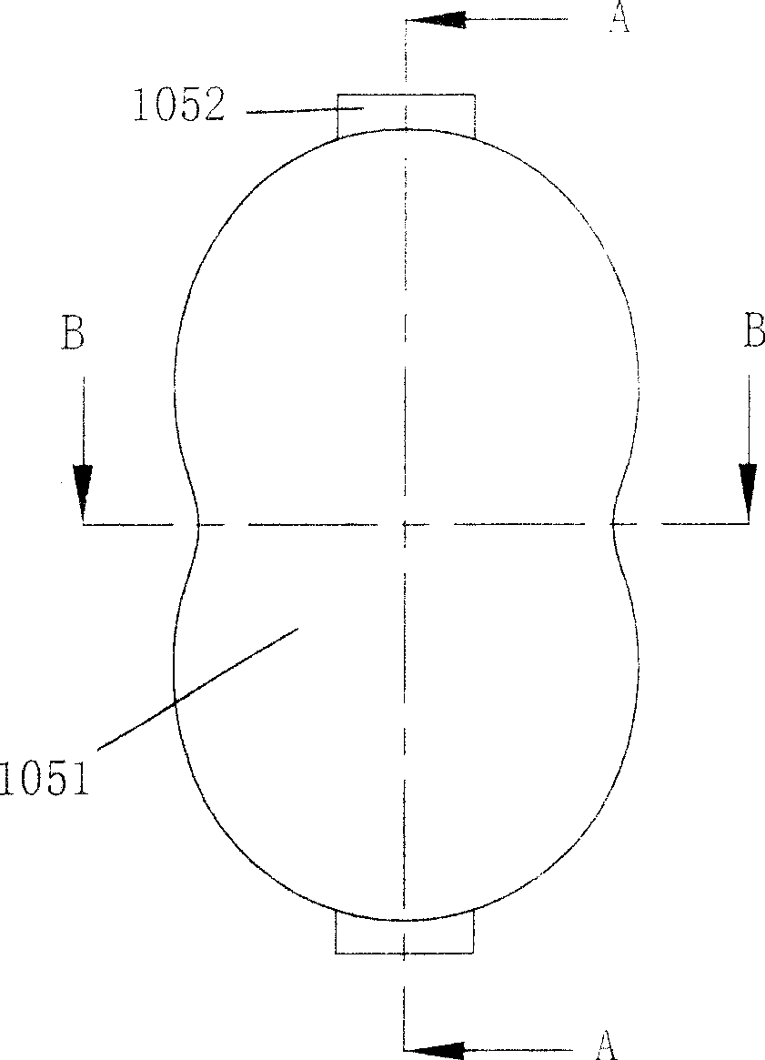
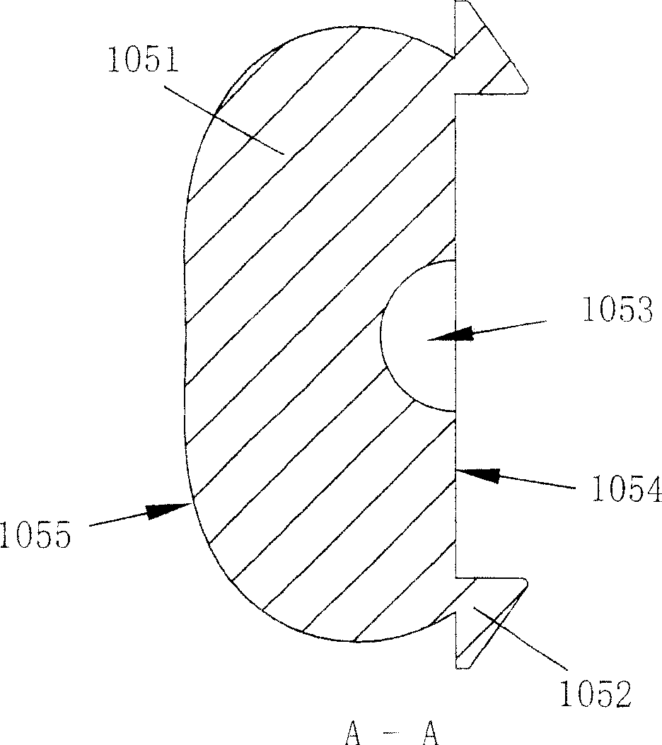
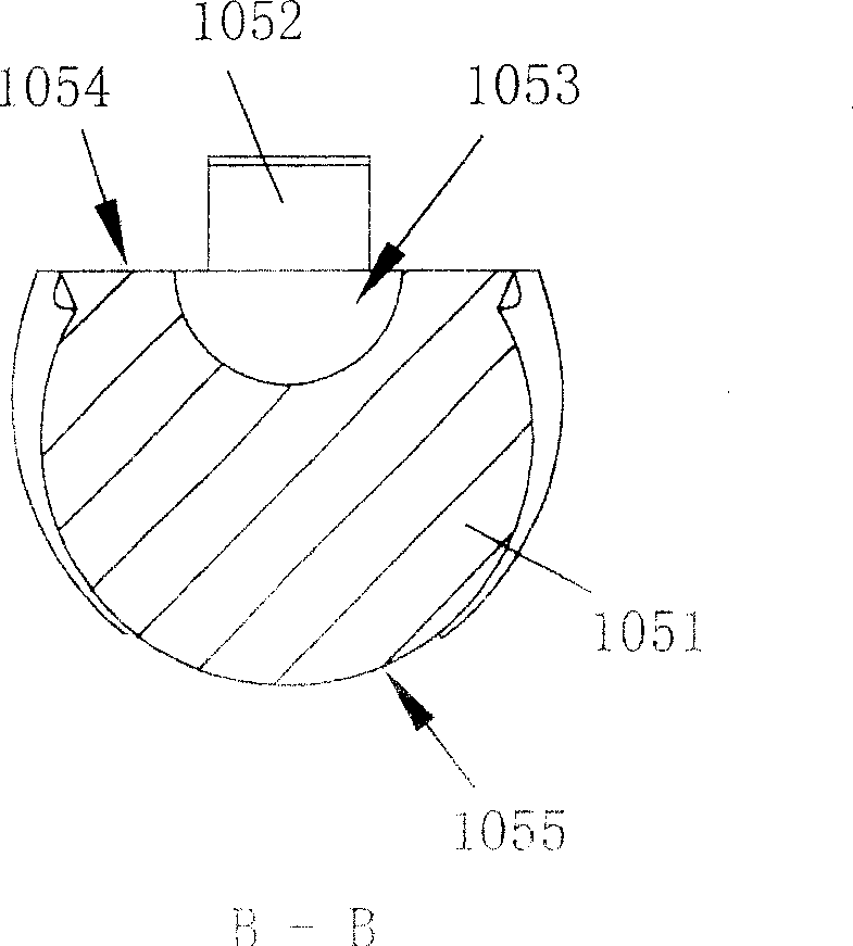
[0031] The present invention will be described in further detail below in conjunction with the accompanying drawings. refer to Figure 1 to Figure 6 , the first embodiment of the utility model is a secondary optical lens 105, which has a base surface 1054, and the base surface 1054 is a plane; The light-emitting surface 1055 intersects with the base surface 1054 to define the outline of the base surface 1054; the center of the base surface 1054 is provided with a light-incident surface 1053, which is a concave surface; the base surface 1054 and the light-incidence surface 1053 1055 and the light-emitting surface jointly define the body 1051 of the secondary optical lens 105; the secondary optical lens 105 also includes a pair of hooks 1052 arranged on the base surface 104 of the body, and the pair of hooks 1052 are respectively arranged on the two longitudinal sides of the base surface 1054. The hook tip of the hook 1052 extends longitudinally along the base surface 1054 to o...


PUM


Abstract

The present invention relates to the LED lighting engineering, in particular to a double optical lens used on a LED street lamp. The double optical lens is characterized in that a base level is provided, and the base level is a plane; a light outgoing face of the lens consists of two partial sphere surfaces and a transition surface between the two partial sphere surfaces; the light outgoing face communicates with the base level to define the outline of the base level; the center of the base level is provided with a light entering face, which is a concave face; the base level, the light entering face, and the light outgoing face together define the body of the double optical lens; the double optical lens also includes a pair of buckle hooks arranged on the base level of the body, the pairs of buckle hooks is respectively arranged on the two vertical edges of the base level; the hook points of the buckle hooks extend out of the base level along the base level; the obverse face of the hook points, namely the face facing to the light outgoing face is the first plane, and the first plane is parallel to the base level. The reverse face of the hook points, namely the face keeping away from the light outgoing face is the second plane, and the second plane is an inclined plane relatively to the first plane. The end extending out of the base level of the second face is the low end.

Description

technical field [0001] The invention relates to LED lighting technology, in particular to a secondary optical lens for LED street lamps. Background technique [0002] In LED lighting technology, in order to improve the light output efficiency of LED and facilitate use, it is generally necessary to package the LED chip once, such as using a ball lens packaging method. For specific applications, such as LED street lighting, it is required to irradiate light intensively in order to form the required light spot, so it is necessary to perform secondary optical treatment on the LED chips (generally called LED bulbs) after primary packaging. The processing method in the prior art is to install a common secondary lens in front of a group of LED light bulbs to achieve the purpose of concentrating light. Using this method for secondary treatment, because a distance must be preset between the LED bulb and the secondary lens, the light entering the secondary lens is already stray light...

Claims


Application Information

Patent Timeline
Patent Type & Authority Patents(China)
IPC IPC(8): G02B3/00G02B1/04F21V5/04
CPCY02B20/72
Inventor 李旭亮
Owner KINGSUN OPTOELECTRONIC CO LTD
Learn More