Device and method for detecting depth of anesthesia

A detection equipment, a technology of anesthesia depth, applied in the field of medical measurement, can solve the problems of low spatial resolution, high cost, poor accuracy and so on

Inactive Publication Date: 2009-05-27
HUAZHONG UNIV OF SCI & TECH
View PDF3 Cites 0 Cited by
  • Summary
  • Abstract
  • Description
  • Claims
  • Application Information

AI Technical Summary

Problems solved by technology

At present, the measurement of human body surface temperature generally uses multiple sensors and multi-point measurements, but this method has low spatial resolution, high cost, and poor accuracy.

Method used


Image

  • Device and method for detecting depth of anesthesia
  • Device and method for detecting depth of anesthesia
  • Device and method for detecting depth of anesthesia

Examples


Embodiment Construction

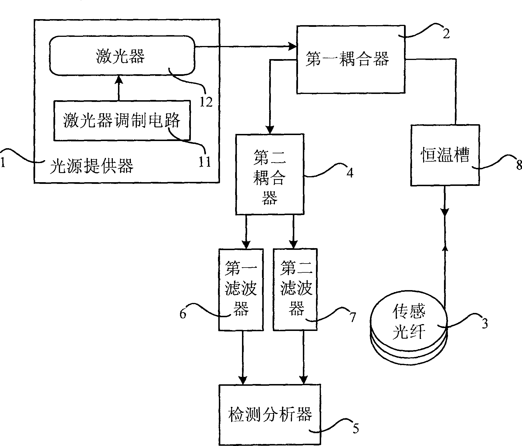
[0047] Such as figure 1 Shown is a structural diagram of the anesthesia depth detection device 1 of the present invention. The testing equipment includes:

[0048] Light source provider 1, the output satisfies the relationship between light pulse width and spatial resolution: ΔL = t w × v g 2 light pulse, where v g is the speed of light in the fiber, t w is the light pulse width;

[0049] The first coupler 2, connected with the light source provider 1, is used to receive the light pulse and output it, and receive the scattered light and output it, the scattered light power P as =Pα as SX(1-X) where α as is the Raman scattering coefficient, S is the backscattering factor and loss, P is the input optical power, X is the percentage of input optical power and output optical power;

[0050] The sensi...


PUM

PropertyMeasurementUnit
wavelengthaaaaaaaaaa

Abstract

The present invention relates to an anelocator equipment. It includes the following several portions: light source provider for providing light pulse; first coupler connected with said light source provider for receiving light pulse and outputting it and receiving scattered light and outputting it; sensing optical fiber connected with said first coupler, the action of light pulse and sensing optical fiber can produce Raman scattering; second coupler connected with said first coupler for dividing the scattered light into anti-stokes light and stokes light according to the light-splitting ratio of 90:10; and detection analyzer connected with second coupler for making signal processing analysis and display.

Description

technical field [0001] The invention relates to the field of medical measurement, in particular to a detection device for detecting the depth of anesthesia. Background technique [0002] Adequate anesthesia is currently necessary for patients undergoing surgery and intensive care to relieve stress. When monitoring the depth of anesthesia for patients who have undergone general anesthesia, auditory evoked potentials and EEG monitoring techniques or a combination of the two are generally used. For patients in a hypnotic state after anesthesia, indirect measurements can be made by observing clinical signs and patient responses to sounds and sensations, including testing of auditory evoked potentials. However, this method described above may arouse responding patients due to stimulation, and it is not suitable for those who cannot respond. Especially since the auditory evoked potential test involves too many afferent pathways and nerves, it is difficult to be accurate and anti...

Claims


Application Information

Patent Timeline
Patent Type & Authority Patents(China)
IPC IPC(8): A61B5/01G01K11/32G01K11/324
Inventor 元秀华
Owner HUAZHONG UNIV OF SCI & TECH
Why Eureka
Try Eureka