Temperature measuring device and temperature measuring method in friction process of friction pair material

A temperature measuring device and friction pair technology, applied in measuring devices, thermometers, measuring heat, etc., can solve the problems of accurate measurement of friction coefficient and wear rate, cumbersome and difficult operation, and non-contact temperature measurement, etc., and achieve reliable data. effect of source

Pending Publication Date: 2021-12-03
WUHAN RES INST OF MATERIALS PROTECTION
View PDF6 Cites 0 Cited by
  • Summary
  • Abstract
  • Description
  • Claims
  • Application Information

AI Technical Summary

Problems solved by technology

Non-contact temperature measurement is easily affected by ambient temperature and humidity, and the emissivity of the target surface must be known
At present, the commonly used contact temperature measurement usually uses temperature measurement components embedded in the friction pair materi

Method used


Image

  • Temperature measuring device and temperature measuring method in friction process of friction pair material
  • Temperature measuring device and temperature measuring method in friction process of friction pair material
  • Temperature measuring device and temperature measuring method in friction process of friction pair material

Examples


Embodiment 1

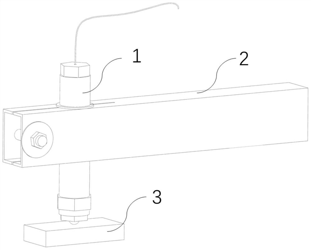
[0032] Example 1: The following spherical sample is used as the friction pair material, and the friction and wear test is carried out with the pair of the German Evonik P84NT1 polyimide molded product pair, and the temperature of the friction pair material of the spherical sample is measured by the temperature measuring component 17 The change.

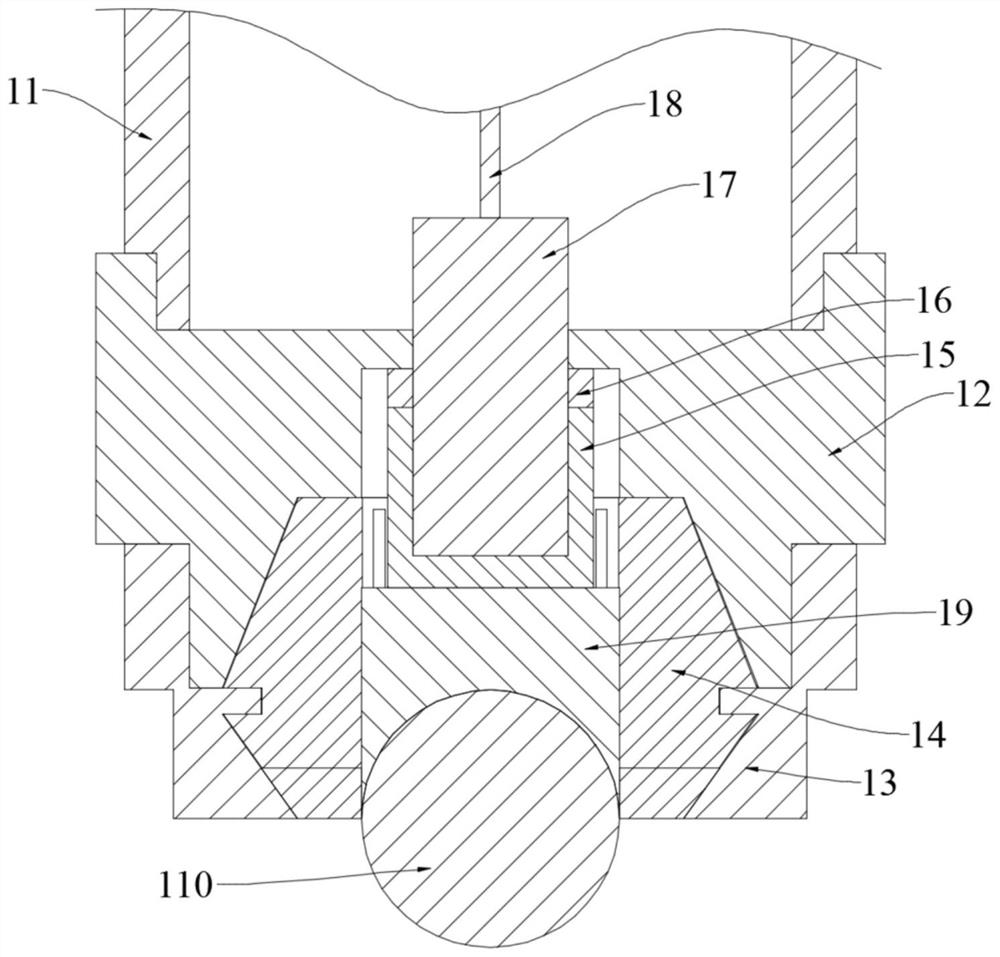
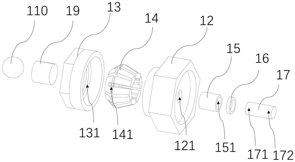
[0033] Such as Figure 1 to Figure 5 As shown, the present invention discloses a temperature measuring device, which includes a hollow base 12 , an extension rod 11 , a locking cap 13 , a snap spring 14 , a top post 15 , and a temperature measuring component 17 . The connection relationship is as follows: the locking cap 13 and the snap spring 14 are buckled and connected through the convex ring 131 and the annular slot 141, and the upper and lower ends of the hollow base 12 are respectively connected with the locking cap 13 and the extension rod 11 by bolts. The cap 13 locks the circlip 14 to clamp the material of the friction pair ...

Embodiment 2

[0044] Embodiment 2: Others are the same as in Embodiment 1, the difference is that the test object of this embodiment is a cylindrical friction pair 20, so this embodiment omits the concave hemispherical support column 19, and the cylindrical friction pair 20 is directly in contact with the top column 15 .

[0045] The temperature measuring device 1 of the present invention is not only capable of testing spherical geometric samples and cylinders, but also can test the temperature changes during the friction and wear process of cones, cubic friction pair materials and the like. According to different shapes of the friction pair, select the corresponding support column to contact the top column 15, and improve the thermal conductivity through the support column, so as to solve the problem of insufficient thermal conductivity of the material of the friction pair and the top column 15 in direct contact.


PUM


Abstract

The invention discloses a temperature measuring device and method in the friction process of a friction pair material, the temperature measuring device comprises a hollow base, an extension rod, a locking cap, a snap spring, a top column and a temperature measuring component, the hollow base is connected with the locking cap and the extension rod, the locking cap locks the snap spring to clamp the top column, the temperature measuring end of the temperature measuring component is embedded into the top column, a lead end penetrates through a through hole of the hollow base, a lead at the lead end of the temperature measuring component penetrates through a through hole in the top end of the extension rod and is connected into a data acquisition instrument to test the real-time temperature change of the friction pair material in the friction process. Compared with a mode of measuring the temperature by destroying the intrinsic structure of the friction pair material, the temperature measuring method provided by the invention does not damage a research object, and is suitable for friction pair materials of various geometric dimensions.

Description

technical field [0001] The invention belongs to the detection field of friction and wear testing machines, and relates to a temperature measurement technology for friction pair materials, in particular to a temperature measuring device and a temperature measurement method during the friction process of friction pair materials, which can non-destructively detect friction pair materials in the friction and wear process temperature change. Background technique [0002] The friction and wear testing machine mainly determines the anti-friction and anti-wear properties of the material application by detecting the friction coefficient and wear rate of the material. During the rotation or reciprocating motion of the friction pair material, based on the material, roughness, and mechanical properties of the counterpart material, as well as the environment in the friction process, frictional thermal effects will inevitably occur on the contact surface. The generation, accumulation and...

Claims


Application Information

Patent Timeline
IPC IPC(8): G01K13/00G01K1/14G01N3/56
CPCG01K13/00G01K1/14G01N3/56
Inventor 段海涛万长鑫李健贾丹詹胜鹏杨田李银华凃杰松
Owner WUHAN RES INST OF MATERIALS PROTECTION
Why Eureka
Try Eureka