Working layer refractory brick piling structure restraining splashing and nodulation of RH vacuum tank

A vacuum tank and working layer technology, applied in the field of iron and steel metallurgical refining, can solve the problems of affecting the cleanliness of molten steel, matching the production rhythm of shadow refining, and poor sealing of vacuum tanks, so as to improve the efficiency of RH refining and reduce internal nodules , The effect of prolonging the continuous processing time of RH

Pending Publication Date: 2019-11-05
UNIV OF SCI & TECH BEIJING
View PDF0 Cites 0 Cited by
  • Summary
  • Abstract
  • Description
  • Claims
  • Application Information

AI Technical Summary

Problems solved by technology

The connection between the upper tank and the lower tank of the RH needs to be connected by flanges. Since the flanges are steel products, long-term exposure to high temperatures will cause deformation of the flanges, making the sealing of the vacuum tank not strong. It is necessary to add a water cooling device around it. To avoid the deformation of the flange, but in actual production, the temperature of the joint position is low due to water cooling, and the splashed molten steel adheres to the upper and lower positions of the joint due to chilling. With the increase of the service life of RH, the joint position The cold steel becomes thicker and thicker, and there is a risk of falling off at any time. In actual on-site production, the cold steel at the joints has fallen off as a whole, resulting in abnormal composition of the molten steel, so that returning to the LF furnace to readjust the composition of the molten steel will seriously affect the refining process. Production rhythm matching in the steel process, RH efficient production
The content of carbon, oxygen and hydrogen in cold steel nodules is high and unstable, and the shedding and reaction of nodules can easily cause abnormal composition of molten steel, affecting the cleanliness of molten steel, and the temperature of cold steel nodules is low, falling Into the steel may make the molten steel temperature abnormal, affecting the actual production

Method used


Image

  • Working layer refractory brick piling structure restraining splashing and nodulation of RH vacuum tank
  • Working layer refractory brick piling structure restraining splashing and nodulation of RH vacuum tank
  • Working layer refractory brick piling structure restraining splashing and nodulation of RH vacuum tank

Examples


Embodiment 1

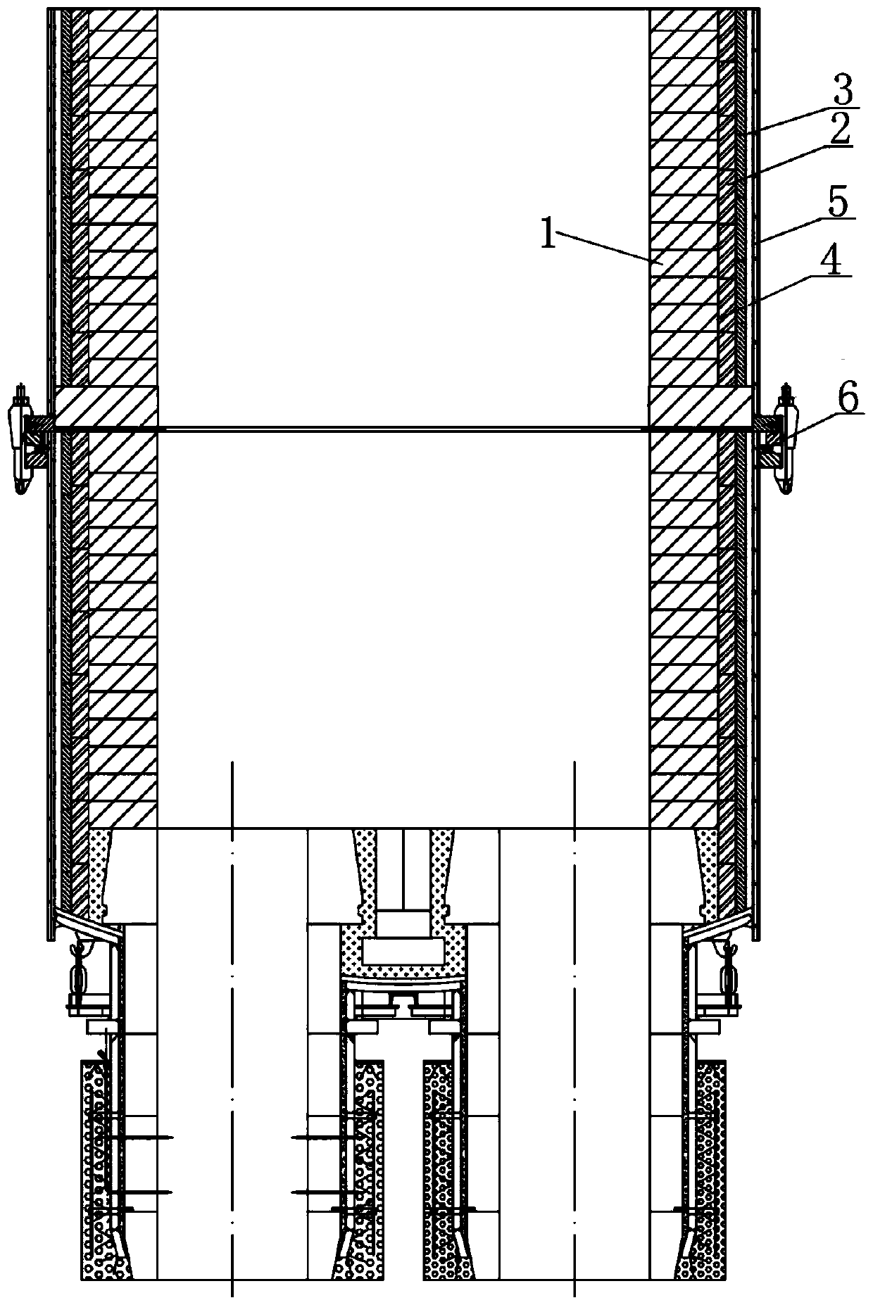
[0050] Such as figure 1 As shown, the inner side of the refractory bricks in the working layer in the prior art is a smooth and straight stacked structure, and the connection position between the upper tank body and the lower tank body of the RH vacuum tank needs to be connected by a flange, because the flange is a steel product Long-term exposure to high temperature will lead to deformation of the flange, making the sealing of the vacuum tank not strong. It is necessary to add a circle of water cooling devices around to avoid deformation of the flange. However, in actual production, the temperature of the joint position is low due to water cooling, and the spray The splashed molten steel adheres to the upper and lower positions of the seam due to intense cooling. As the service life of RH increases, the cold steel at the seam becomes thicker and thicker, and there is a risk of falling off at any time. In the actual on-site production, there are seams The cold steel falls off ...

Embodiment 2

[0065] The refractory brick stacking structure of the working layer that suppresses the splashing and nodulation of the RH vacuum tank body in this embodiment is basically the same as that in Embodiment 1, except that:

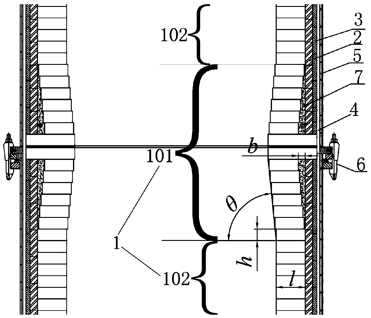
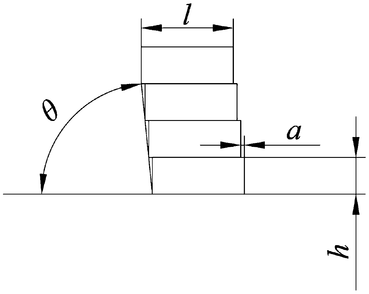
[0066] The included angle between the raised portion and the horizontal line is not more than 86° and not less than 80°. This range of included angles can effectively suppress the splashing and nodulation of the RH vacuum tank body. If the angle is less than 80°, it will cause damage to the refractory bricks. For the safety of stacking, when the angle is greater than 86°, the effect of suppressing the splashing and nodulation of the RH vacuum tank will be reduced or even not suppressed.

Embodiment 3

[0068] The refractory brick stacking structure of the working layer that suppresses the splashing and nodulation of the RH vacuum tank body in this embodiment is basically the same as that in Embodiment 2, except that:

[0069] The thickness b of the thickest part of the heat insulating material (that is, the maximum offset of the refractory brick in the vertical direction) is 50 mm.


PUM

PropertyMeasurementUnit
thicknessaaaaaaaaaa
thicknessaaaaaaaaaa
thicknessaaaaaaaaaa

Abstract

The invention belongs to the technical field of ferrous metallurgy refining and particularly relates to a working layer refractory brick piling structure restraining splashing and nodulation of an RHvacuum tank. Through the working layer refractory brick piling structure, splashing and nodulation of the RH vacuum tank are lowered. The working layer refractory brick piling structure comprises a convex part and a vertical part. The vertical part extends to the two ends from the convex part. The convex part and the vertical part are obtained by piling refractory bricks. Compared with an existingpiling structure, the working layer refractory brick piling structure can achieve the effect that nodulation is not liable to occur to the RH vacuum tank. The piling mode is changed, gaps produced inthe piling process are used for installing thermal insulation materials, and heat transferred to a flange outside the furnace wall from the RH inner wall can be reduced. In addition, thermocouples are installed in the thermal insulation materials and are used for detecting the temperature of the RH furnace wall, if the temperature is lower than the temperature of easy-cold steel, furnace wall baking can be selected so as to reduce cold steel, and the purpose of temperature control of the RH tank is achieved.

Description

technical field [0001] The invention belongs to the technical field of metallurgical refining of iron and steel, and in particular relates to a stacking structure of refractory bricks in a working layer for suppressing splashing and nodulation of an RH vacuum tank body. Background technique [0002] RH external refining plays an important role in connecting the past and the future and adjusting the production rhythm in the whole steelmaking system. The connection between the upper tank and the lower tank of the RH needs to be connected by flanges. Since the flanges are steel products, long-term exposure to high temperatures will cause deformation of the flanges, making the sealing of the vacuum tank not strong. It is necessary to add a water cooling device around it. To avoid the deformation of the flange, but in actual production, the temperature of the joint position is low due to water cooling, and the splashed molten steel adheres to the upper and lower positions of the ...

Claims


Application Information

Patent Timeline
Patent Type & Authority Applications(China)
IPC IPC(8): C21C7/10
CPCC21C7/10
Inventor 王敏宋磊包燕平
Owner UNIV OF SCI & TECH BEIJING
Why Eureka
Try Eureka