Double row burner for roaster

A combustion device and roasting furnace technology, applied in furnaces, furnace components, lighting and heating equipment, etc., can solve problems affecting product quality uniformity, uneven temperature field distribution, high energy consumption of furnaces, etc., to achieve more uniform temperature, The effect of increasing temperature and reducing energy consumption

Inactive Publication Date: 2009-06-03
GUIYANG AL-MG DESIGN & RES INST
View PDF7 Cites 0 Cited by
  • Summary
  • Abstract
  • Description
  • Claims
  • Application Information

AI Technical Summary

Problems solved by technology

The combustion device is a single row of burners, which are installed in the front of the furnace chamber opposite to the fire well, and inject fuel to the fire well in the furnace through the burner opening on the furnace cover. The length direction of the chamber (that is, the direction of flue gas flow) produces a large temperature difference, which makes the temperature field distribution and unevenness in the entire furnace chamber, thus affecting the uniformity of product quality
And the furnace consumes a lot of energy

Method used


Image

  • Double row burner for roaster
  • Double row burner for roaster

Examples


Embodiment Construction

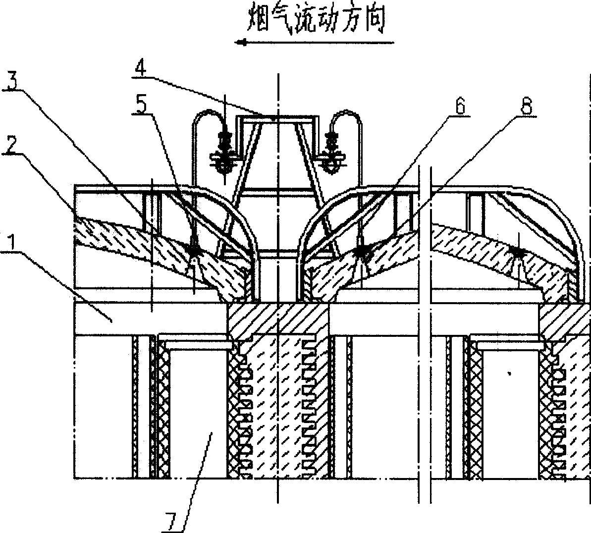
[0012] Embodiments of the present invention: on the furnace cover (2) of the furnace chamber (1), there are burner mouths (3), (8) (formerly used as observation holes), and the combustion device (4) is movable, mounted on Between the front and back furnace covers (2), the main burner (5) and the newly added auxiliary burner (6) are respectively connected through two fuel pipes. Main burner (5) is contained in the burner mouth (3) facing fire well (7), and auxiliary burner (6) is contained in the burner mouth (8) of preceding furnace cover (2) rear portion.

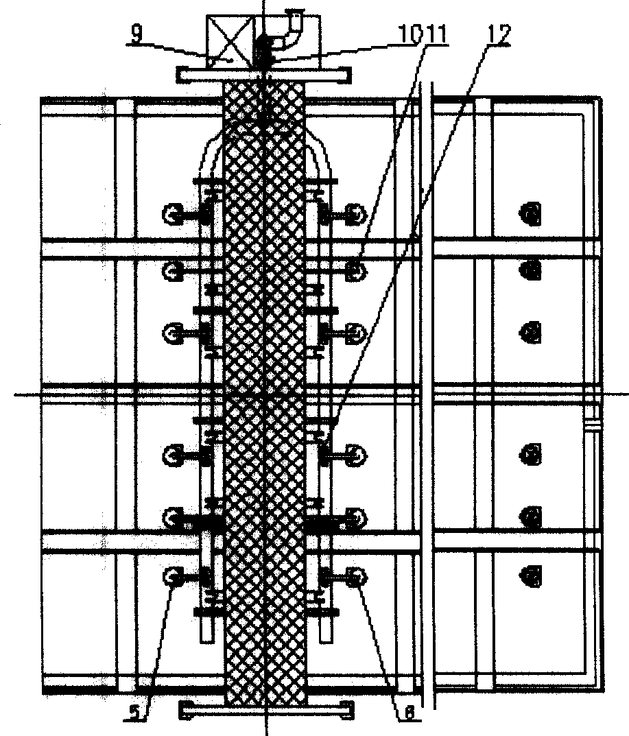
[0013] The control cabinet (9) is installed at the end of the combustion device (4), and a pressure sensor (10) and a pulse solenoid valve (12) are installed on the combustion device (4); a temperature sensor ( 11).


PUM


Abstract

The invention includes a furnace chamber and a furnace lid, on which there is a nozzle mouth. A combustion apparatus mounted between the front and back furnace lids is connected with a nozzle and a secondary nozzle. The nozzle is mounted in the nozzle mouth which is facing to a gas well. The secondary nozzle is mounted in the nozzle mouth at the back of the furnace lid in the preceding heating furnace chamber.

Description

Technical field: [0001] The invention relates to a combustion device of a roasting furnace, in particular to a double-row combustion device of a roasting furnace. Background technique: [0002] The traditional covered ring roaster consists of several heating furnace chambers, preheating furnace chambers, and cooling furnace chambers to form a combustion system (the flue gas flow direction is from front to back). The combustion device is placed above the furnace cover between the two heating furnace chambers. The combustion device is a single row of burners, which are installed in the front of the furnace chamber opposite to the fire well, and inject fuel to the fire well in the furnace through the burner opening on the furnace cover. The length direction of the chamber (that is, the direction of flue gas flow) produces a large temperature difference, which makes the temperature field distribution and unevenness in the entire furnace chamber, thereby affecting the uniformity...

Claims


Application Information

Patent Timeline
Patent Type & Authority Patents(China)
IPC IPC(8): F27B3/20F27D1/18
Inventor 高国庆
Owner GUIYANG AL-MG DESIGN & RES INST
Why Eureka
Try Eureka