Supercharge Your Innovation With Domain-Expert AI Agents!

Angular velocity sensor

A technology of angular velocity sensor and amplifier, which is applied in the direction of instrument, gyro effect for speed measurement, speed/acceleration/shock measurement, etc.

Inactive Publication Date: 2009-06-03
PANASONIC CORP
View PDF5 Cites 0 Cited by
  • Summary
  • Abstract
  • Description
  • Claims
  • Application Information

AI Technical Summary

Problems solved by technology

[0004] However, the existing angular velocity sensor has the following problem: in order to perform abnormal diagnosis and reduce the error of angular velocity detection, the signal input electrodes 105, 106 for abnormal diagnosis and the reference potential ground must be provided on the X1 surface of the tuning fork vibrator 100 at the same time. Electrodes 107, 108

Method used


Image

  • Angular velocity sensor
  • Angular velocity sensor
  • Angular velocity sensor

Examples


Embodiment approach

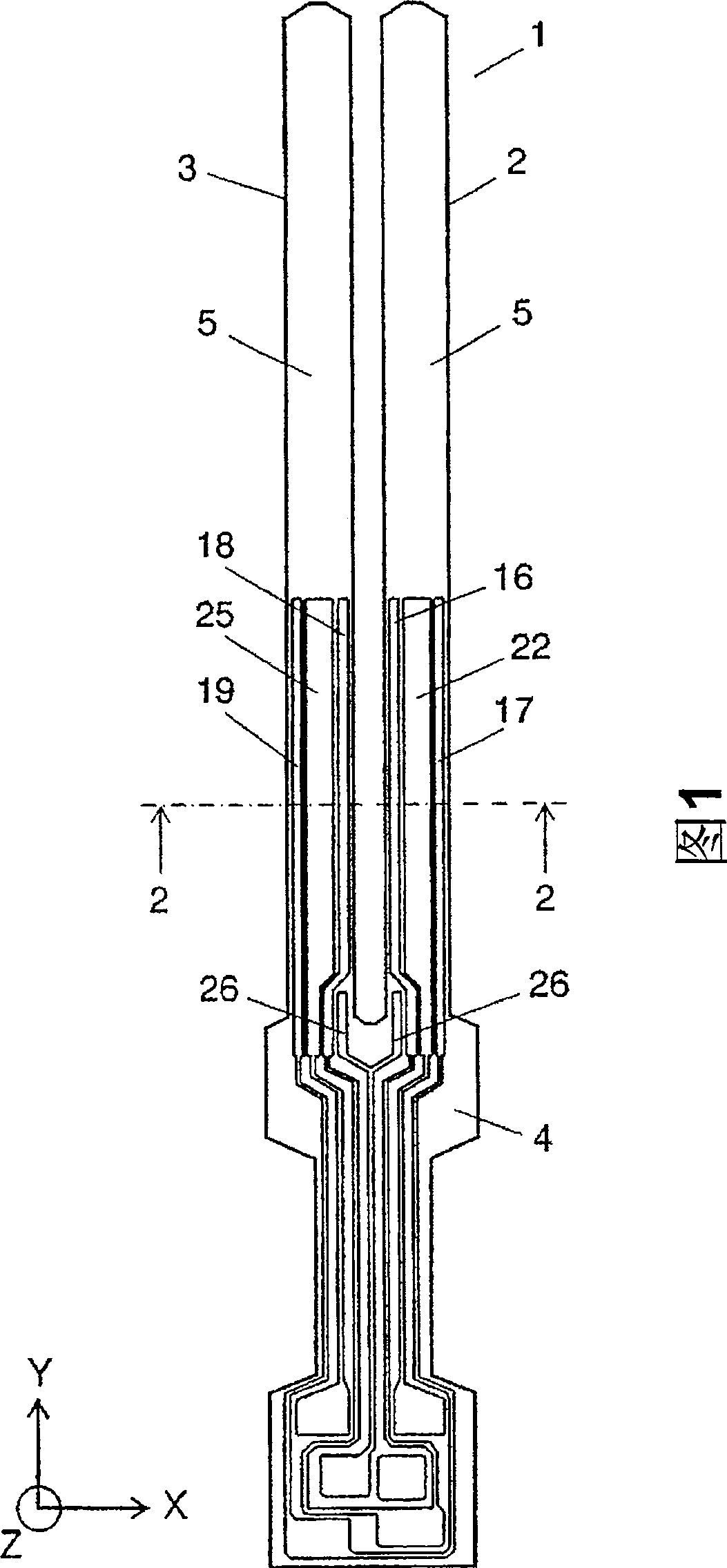
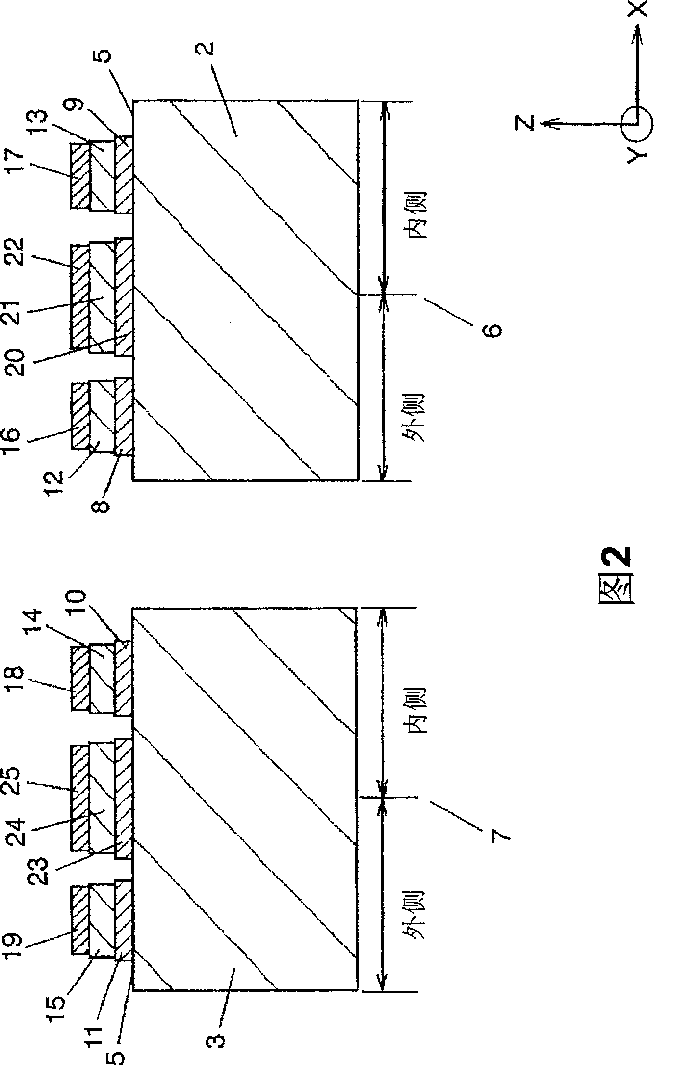
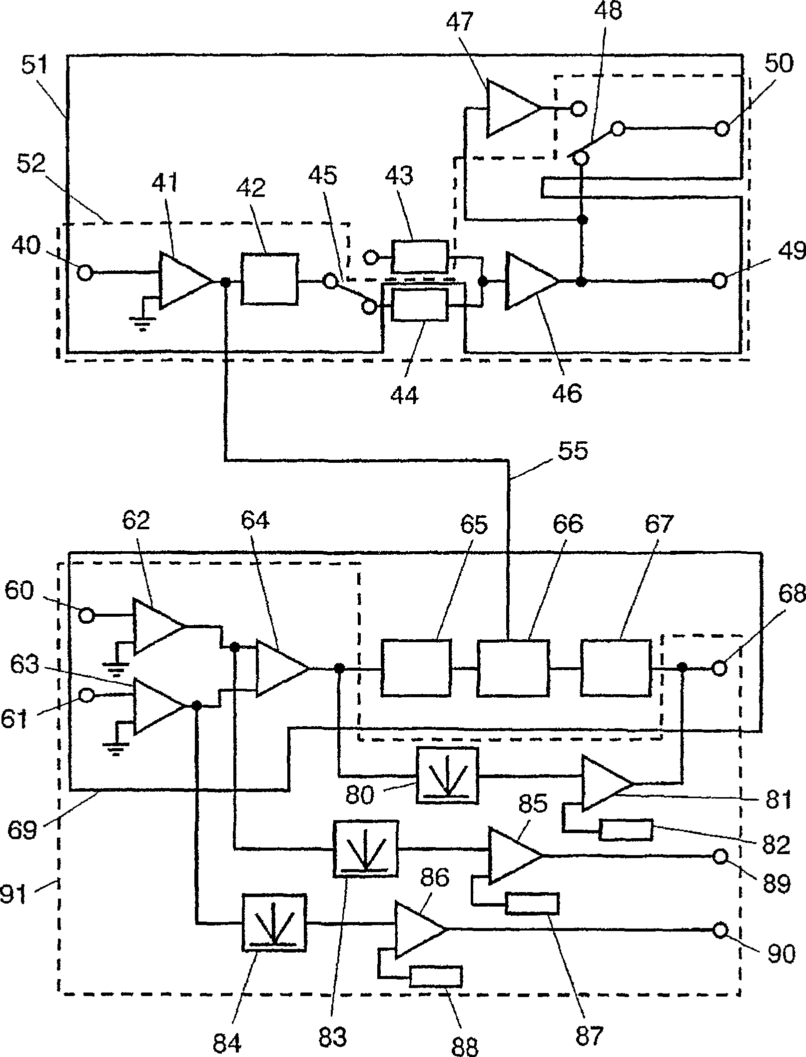
[0074] FIG. 1 is a configuration diagram of a tuning fork vibrator of an angular velocity sensor according to an embodiment of the present invention. FIG. 2 is a 2-2 sectional view of the vibrator shown in FIG. 1 . image 3 is a circuit block diagram of the angular velocity sensor in the same embodiment.

[0075] In FIGS. 1 and 2 , a tuning fork vibrator 1 made of silicon, which is a non-piezoelectric material, has arms 2 and 3 . Furthermore, the tuning fork vibrator 1 further has a base 4 . Furthermore, the arms 2 , 3 have a main surface 5 .

[0076] Front view 2, with arm 2 and arm 3 shown on its right and left, respectively.

[0077] First, note arm 2 , shown with centerline 6 . The center line 6 indicates the position of the approximately exact center of the arm 2 . A first electrode 8 serving as a common electrode is provided on the inner side of the central line 6 , that is, on the upper surface of the main surface 5 closest to the arm 3 . A first piezoelectric film...


PUM


Abstract

The present invention provides an angular velocity sensor that can diagnose abnormalities without having on a tuning fork vibrator special abnormality diagnostic signal input electrodes or reference potential ground electrodes to reduce errors in detecting angular velocity. Switches are used to generate drive signals of the same phase at output terminals, thereby bending arms in the Z-axis direction of tuning fork vibrator 1. The electric charges generated from tenth electrode and 12th electrode formed respectively on arms are amplified respectively at first amplifier and second amplifier. The outputs of these amplifiers are inputted to differential amplifier, whose output is compared by comparator with a prescribed value generated by reference value generator. When the output exceeds the prescribed value, comparator determines an abnormality.

Description

technical field [0001] The present invention relates to an angular velocity sensor with an abnormality detection function. Background technique [0002] As a conventional angular velocity sensor of this kind, it is introduced in, for example, Japanese Laid-Open Patent Publication No. 2000-88584. 4B, 4C, 4A, and 4D are development views of electrodes formed on the outer peripheral surface of the vibrator seen from the front, rear, left and right sides of the vibrator described in JP-A-2000-88584. In these figures, driving electrodes 101 and 102 are respectively provided on the X1 surface which is one main surface of the tuning fork vibrator 100 made of piezoelectric ceramics. Angular velocity detection electrodes 103 , 104 are respectively provided on Y1 , Y2 surfaces that are side surfaces of the tuning fork vibrator 100 . Abnormality diagnosis signal input electrodes 105 and 106 are provided near the inner side of the X1 surface on the arm of the tuning fork vibrator 100 ...

Claims


Application Information

Patent Timeline
Patent Type & Authority Patents(China)
IPC IPC(8): G01C19/56G01P9/04G01C19/5614G01P21/02
CPCG01C19/5614
Inventor 大内智黑田启介山本毅
Owner PANASONIC CORP
Features
  • R&D
  • Intellectual Property
  • Life Sciences
  • Materials
  • Tech Scout
  • Unparalleled Data Quality
  • Higher Quality Content
  • 60% Fewer Hallucinations
Learn More