
Automatic synthesizing device for network control broadcast

A combined device and automatic synthesis technology, which is applied in the branch offices providing special services, data exchange details, electrical components, etc., and can solve the problems of inability to provide remote control broadcasting, large amount of medical guidance information, and inability to meet application requirements.

Inactive Publication Date: 2009-06-24
NANJING NORMAL UNIVERSITY
View PDF3 Cites 0 Cited by
  • Summary
  • Abstract
  • Description
  • Claims
  • Application Information

AI Technical Summary

Problems solved by technology

[0002] Through the analysis and statistics of the currently used broadcasting systems, almost all the systems in use consist of a sound source connected in parallel with N speakers through a power amplifier to form a broadcasting system, using constant voltage or constant resistance. The mode of broadcasting is limited by the broadcasting power amplifier and can only be within a certain area, but this type of method does not enable a speaker to broadcast alone or play different content at the same time or specify the function of playing, let alone provide remote control broadcasting. With the development of digital technology, the existing methods cannot meet the application requirements
[0003] For example: the triage guidance system in the outpatient department of a hospital. With the popularization of digital technology, outpatient doctor workstations have begun to be widely used. The number of patients is increasing, and the amount of medical guidance information is large. When different clinics in the same waiting area call different patients at the same time, it is necessary to Play different medical guidance information at the same time, or when only a certain consulting room is calling for a certain patient, only the broadcast at the door of a certain consulting room should sound, so as to prevent the entire waiting area from broadcasting and affecting the work of doctors in other consulting rooms. This function cannot be realized by existing broadcasting methods

Method used


Image

  • Automatic synthesizing device for network control broadcast
  • Automatic synthesizing device for network control broadcast

Examples


Embodiment Construction

[0012] Below in conjunction with accompanying drawing and embodiment the present invention is described in further detail:

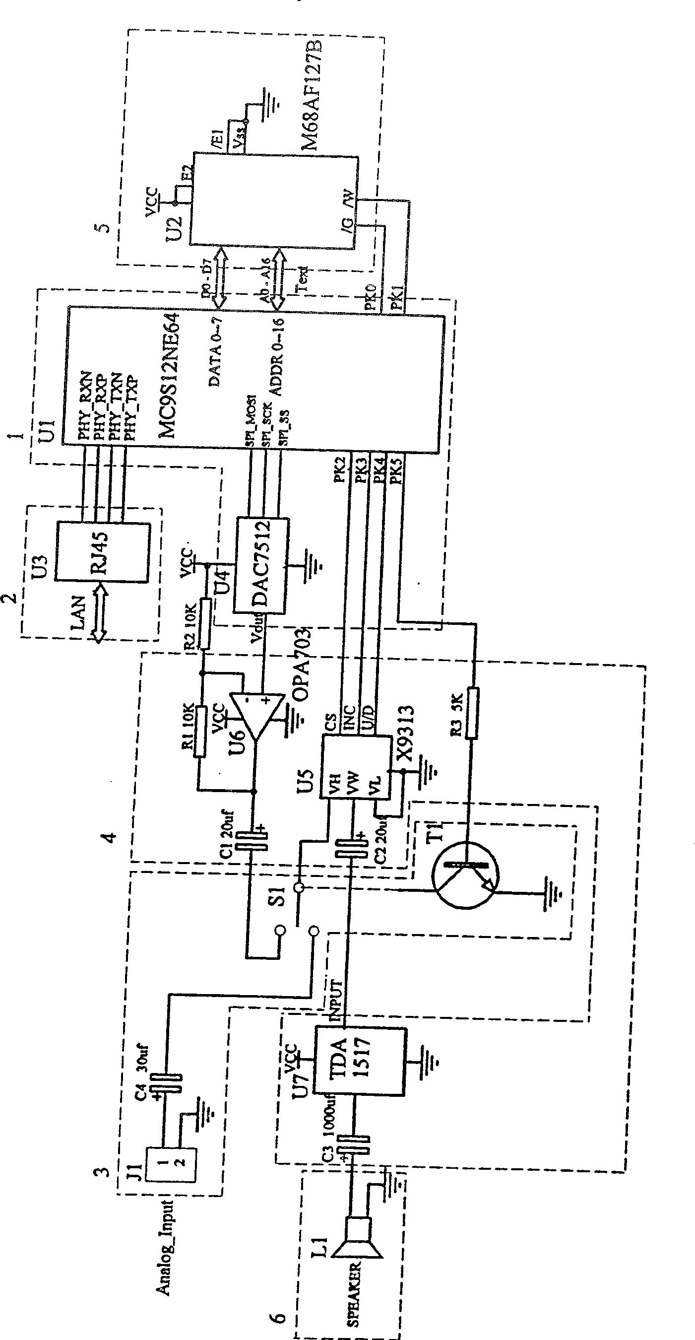
[0013] figure 2 Middle: U1 is MC9S12NE64 for digital signal processing circuit, U2 is M68AF127B for digital signal memory, U3 is RJ45 for digital signal transmission interface circuit, U4 is DAC7512 for external A / D converter, U5 is X9313 for digital potentiometer, U6 is OPA703 It is an audio amplifier, U7 is a TDA1517 audio power output circuit,

[0014] S1 is a relay, T1 is a control switch, J1 is an analog signal interface, and L1 is an audio output speaker.

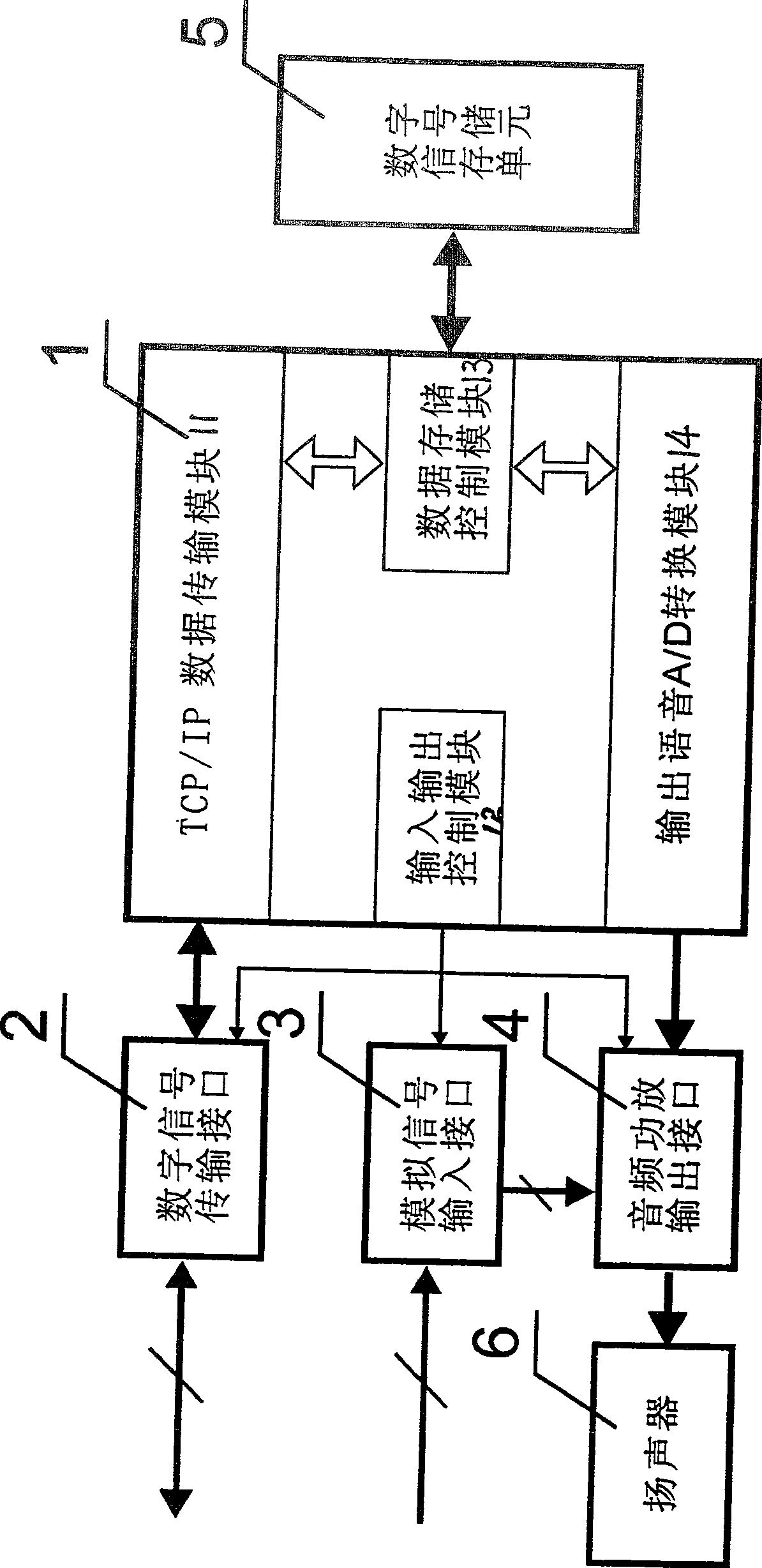
[0015] The present invention is realized like this ( figure 1 As shown): the device includes a digital signal processor 1, a digital signal transmission interface 2, an analog signal transmission interface 3, an audio power amplifier output interface 4, a digital signal storage unit 5, and a speaker 6; the device is centered on the digital signal processor 1 , the TCP / IP data transmission mo...


PUM


Abstract

The network controlled broadcast automatic synthesized combined apparatus is device for playing and controlling voice at remote fixed position. The apparatus uses digital signal processor (DSP) as center. TCP / IP data transmission module in DSP is connected to transmission interface of digital signals. Data memory control module in DSP is connected to digital signal memory unit. The output end of input / output control module in DSP is connected to the input end of transmission interface of analog signals. Output end of output voice A / D conversion module and output end of transmission interface of analog signals are connected to the input ends of audio power amplifier output interface (APAOI). Output end of loudspeaker of APAOI can work according to current system broadcast mode or can accomplish combination of automatic synthesizing single channel, multipoint, asynchronous voice under control by received data.

Description

technical field [0001] The invention discloses a combination device for realizing network-controlled voice automatic synthesis. The device eliminates the need to add complex and expensive control equipment to the existing loudspeaker, uses the existing network resources to realize voice remote playback, and simultaneously realizes the same content and the same content of N broadcasting points. Simultaneous broadcast of different content. Background technique [0002] Through the analysis and statistics of the currently used broadcasting systems, almost all the systems in use consist of a sound source connected in parallel with N speakers through a power amplifier to form a broadcasting system, using constant voltage or constant resistance. The mode of broadcasting is limited by the broadcasting power amplifier and can only be within a certain area, but this type of method does not enable a speaker to broadcast alone or play different content at the same time or specify the f...

Claims


Application Information

Patent Timeline
Patent Type & Authority Patents(China)
IPC IPC(8): H04L12/16H04S7/00
Inventor 陈战平
Owner NANJING NORMAL UNIVERSITY
Learn More