Supercharge Your Innovation With Domain-Expert AI Agents!

Pin shaft milling special-purpose milling machine

A special milling machine, milling technology, applied in milling machine equipment, milling machine equipment details, large fixed members, etc., can solve the problems of cumbersome operation, low work efficiency, backward design, etc.

Inactive Publication Date: 2009-07-08
李健
View PDF7 Cites 0 Cited by
  • Summary
  • Abstract
  • Description
  • Claims
  • Application Information

AI Technical Summary

Problems solved by technology

The design of traditional milling machines is backward, the operation is cumbersome, and the work efficiency is low. The production of pin shaft milling has always been a time-consuming and energy-consuming process in mechanical processing.

Method used


Image

  • Pin shaft milling special-purpose milling machine
  • Pin shaft milling special-purpose milling machine

Examples


Embodiment Construction

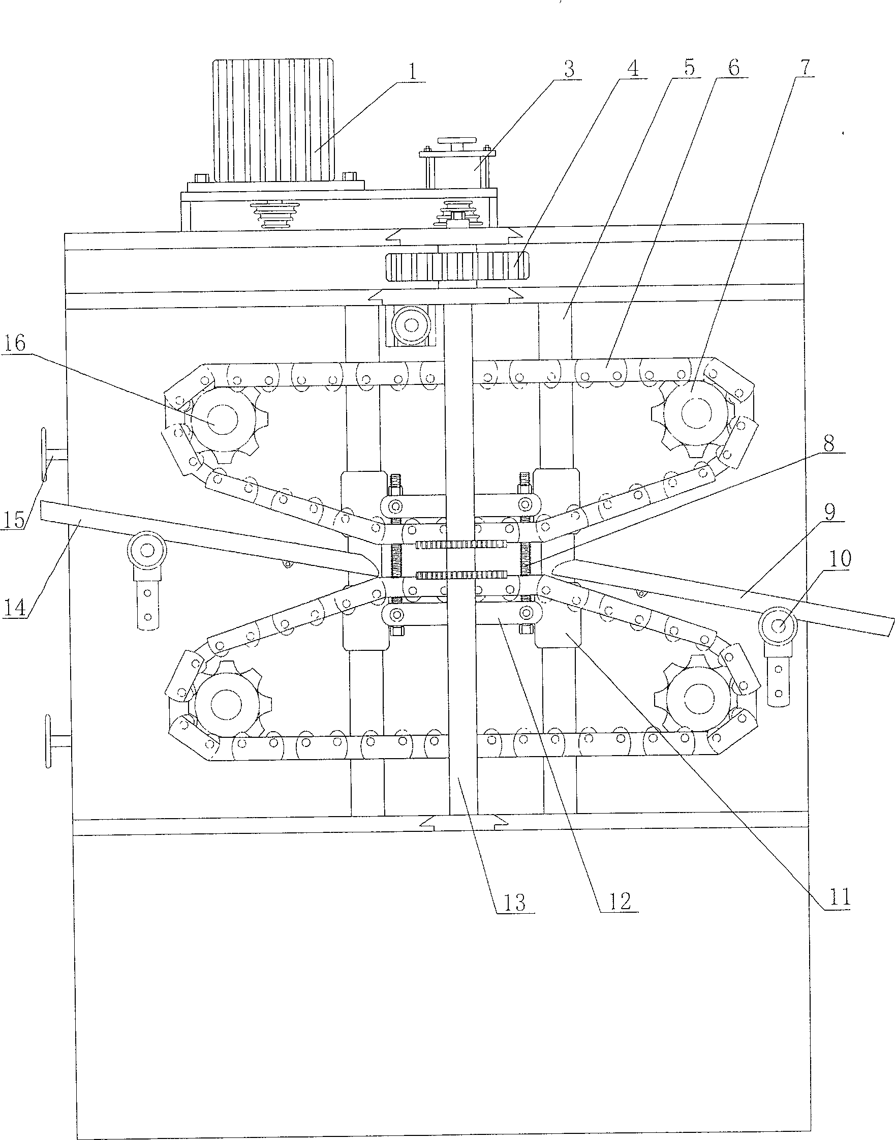
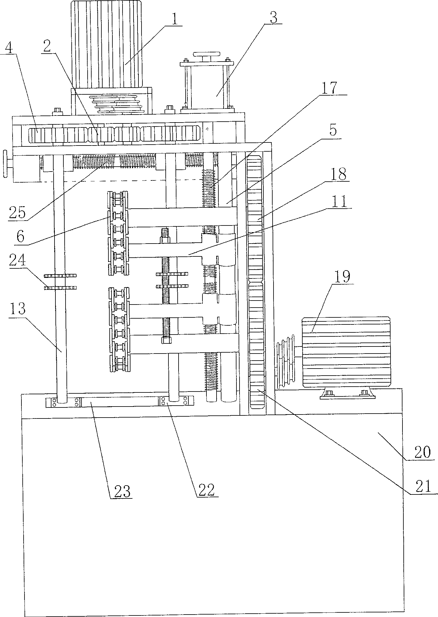
[0011] Such as figure 1 , 2 A special milling machine for pin shaft milling is shown, which mainly includes a bed 20, a positioning feeder 14, a positioning discharger 9, a chain clamp transmission device, a guide rail clamp locking transmission device, and a double-spindle cutter bar transmission device , the chain clamp transmission device includes a motor 19 through a belt drive pinion 21, the pinion drives the meshed main sprocket coaxial bull gear 18, and the main sprocket coaxial coaxial bull gear is coaxially connected to a group of spaced apart main gears. Sprocket 7, the main sprocket drives the auxiliary sprocket 16 through the chain clamp 6, and the auxiliary sprocket adjusting screw 15 adjusts the distance between the auxiliary sprocket 16 and the main sprocket 7, controls and locks the tightness of the chain clamp, and the auxiliary chain The outside of wheel 16 is equipped with location feeder 14, and the outside of main sprocket 7 is equipped with location feed...


PUM


Abstract

The present invention is one milling machine specially for milling pin shaft. The milling machine includes one chain type fixture driving unit, one rail bond locking driving unit, one double spindle tool bar driving unit, one positioning feeder and one positioning discharger. After the double spindle tool bar driving unit is started, the pin shafts to be milled and sliding from the bin of the positioning feeder to the fixture driving unit are clamped in the chain type fixture by the rail bond locking driving unit, moved in even rate and milled continuously by the milling cutter, and the well milled pin shafts are fed by the chain type fixture to the positioning discharger. The milling machine has reasonable structure, simple operation, automatic milling of pin shafts, low power consumption and high efficiency.

Description

Technical field [0001] The invention relates to a milling machine, in particular to a special milling machine for milling pin shafts. Background technique [0002] At present, a single clamp is used to clamp a single pin for milling in the process of milling the pin, and then exit the milling range. The design of traditional milling machines is backward, the operation is cumbersome, and the work efficiency is low. The milling production of pin shafts has always been a time-consuming and energy-consuming process in mechanical processing. Contents of the invention [0003] In order to overcome the disadvantages of the prior art, the object of the present invention is to provide a special milling machine for pin milling with reasonable structure, easy operation, low energy consumption, automatic and continuous milling of pins of the same specification at one time, and improved work efficiency. [0004] In order to achieve the above-mentioned technical purpose, the technical ...

Claims


Application Information

Patent Timeline
Patent Type & Authority Patents(China)
IPC IPC(8): B23C3/00B23Q7/16B23Q7/03B23Q5/04B23Q1/25
Inventor 李健
Owner 李健
Features
  • R&D
  • Intellectual Property
  • Life Sciences
  • Materials
  • Tech Scout
  • Unparalleled Data Quality
  • Higher Quality Content
  • 60% Fewer Hallucinations
Learn More