Resin molding machine

A molding machine and resin technology, applied in the coating and other directions, can solve the problem of increasing the number of residual materials, and achieve the effect of reducing the scope, reducing the cost, and simplifying the mechanism

Inactive Publication Date: 2009-07-08
MURATA MFG CO LTD
View PDF1 Cites 1 Cited by
  • Summary
  • Abstract
  • Description
  • Claims
  • Application Information

AI Technical Summary

Problems solved by technology

This shape requirement results in an increased amount of residual material

Method used


Image

  • Resin molding machine
  • Resin molding machine
  • Resin molding machine

Examples


Embodiment Construction

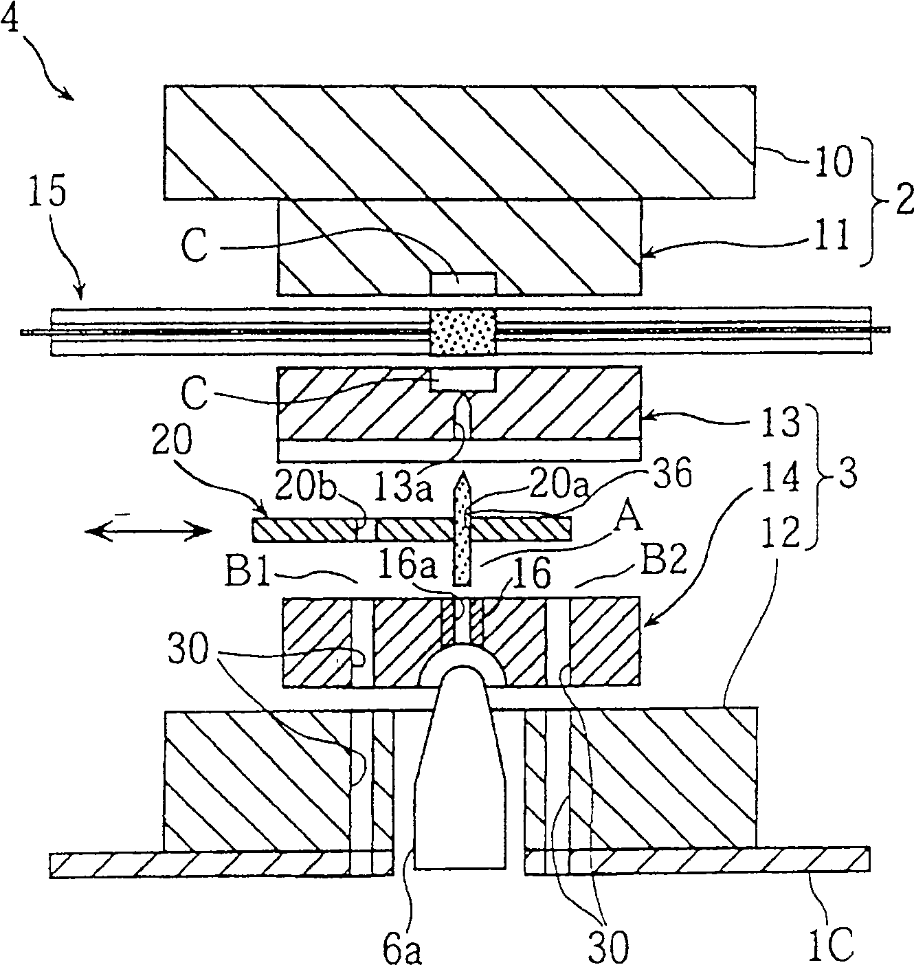
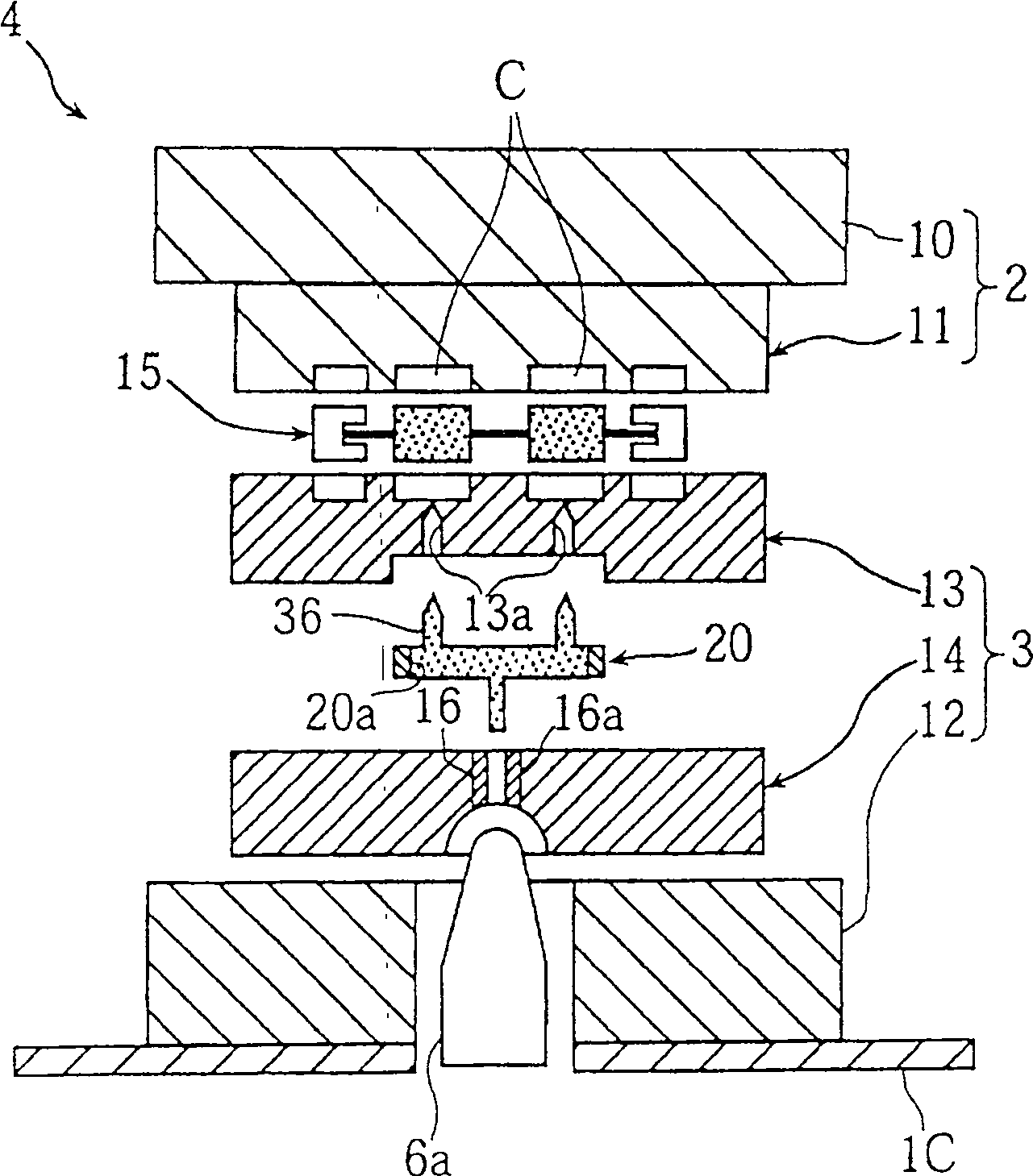
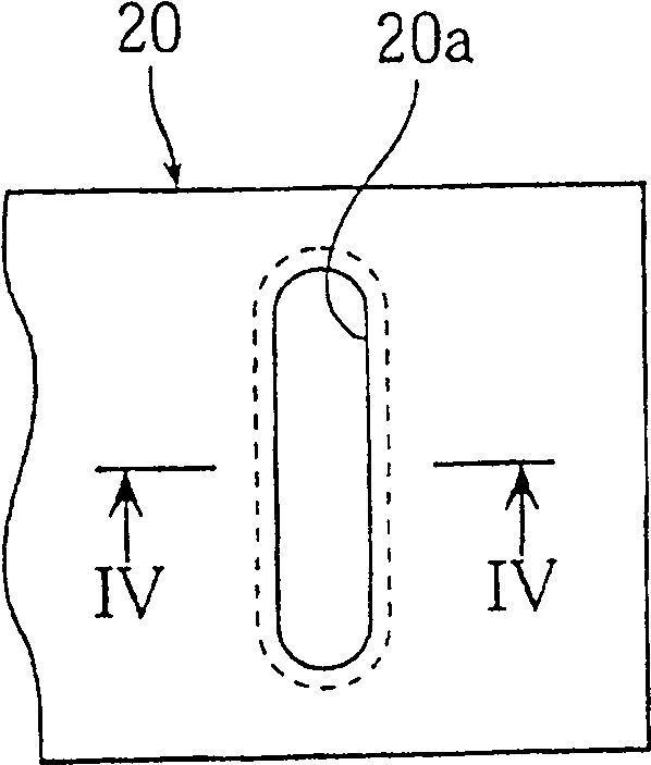
[0049] Figures 1 to 9 A resin molding machine is shown. Figures 1 to 2 are a front sectional view and a side sectional view showing a mold in an open state, respectively. image 3 and 4 Respectively, a plane view and a section view of the channel plate ( image 3 section IV-IV). Figure 5 and 6 is a schematic diagram showing a drive unit of the flow channel plate. Figure 7 This is an overview of the resin molding machine. Figure 8 (a) to (d) and Figure 9 (e) to (g) show a molding process using the mold.

[0050] In these figures, reference numeral 1 denotes a resin molding machine for producing an electronic component made of a thermoplastic resin or a thermosetting resin by injection molding.

[0051] The resin molding machine 1 has a fixed bed 1a on which a mold 4, a mold clamping unit 5, and a molding material delivery unit 6 are provided. The mold 4 includes a movable mold unit 2 and a fixed mold unit 3, The mold clamping unit 5 moves the movable mold unit 2 ...


PUM


Abstract

To provide a resin molding machine capable of reducing cost and capable of reducing cycle time and amount of residual material without requiring a residual material remover, the resin molding machine comprising a pouring tank (13a) communicated with a mold cavity (C) A fixed cavity plate (13), in which is formed a sprue bushing (16) for feeding a molding material into a sprue (16a) of the cavity (C) through the pouring trough (13a), arranged on A flow channel plate (20) between the fixed cavity plate (13) and the gate bushing (16), used for reciprocating the flow channel plate (20) in a straight line through a molding position A between the ejection positions B1 and B2 A cylinder unit (runner plate drive mechanism) (25), the push-out positions B1 and B2 are separated from the molding position A, the push-out position is used to push out residual materials, and a cylinder unit for pushing out residual materials at the push-out positions B1 and B2 is included. Push-out channel (residual material push-out mechanism).

Description

technical field [0001] The present invention relates to a resin molding machine in which a molding material such as a thermoplastic resin and a thermosetting resin is injected from a gate into a cavity through a pouring groove for producing a resin molded article such as a Electronic component. Background of the invention [0002] These resin molding machines typically employ a three-plate, pinpoint-slot mold. [0003] In this model, if Figure 11 and 12 As shown, a mold cavity 53 is formed between the upper surface of a fixed lower mold 51 and the lower surface of a movable upper mold 52 which moves vertically between open / closed positions of the mold. The upper mold 52 has a channel 55 and a pouring groove 54 communicating with the mold cavity 53 . A gate bush 56a which moves vertically and which includes a gate communicating with the runner 55 is provided on the upper surface of the upper mold. [0004] In order to produce a resin molded product using the above resin ...

Claims


Application Information

Patent Timeline
Patent Type & Authority Patents(China)
IPC IPC(8): B29C45/38B29C45/33B29C45/14B29C45/17
CPCB29C45/14655B29C45/1759
Inventor 武田健高桥繁己瀬田邦仁甲斐下仁平
Owner MURATA MFG CO LTD
Why Eureka
Try Eureka