Automobile pedal regulation system

A technology for regulating systems and automobile pedals, which is applied to the layout of vehicle components, foot-operated starting devices, and power plant control mechanisms. Integrate and other issues to achieve the effect of improving driving safety, smooth movement, and improving reliability and safety

Inactive Publication Date: 2009-07-08
BYD CO LTD
View PDF6 Cites 1 Cited by
  • Summary
  • Abstract
  • Description
  • Claims
  • Application Information

AI Technical Summary

Problems solved by technology

[0003] The prior art automotive pedal adjustment system as described in Patent No. US6453767B1 includes a pedal bracket and a pedal strut, the outer end of the pedal strut is connected to the pedal, and also includes two pedal arms, the two pedal arms, the pedal bracket It is respectively hinged with the pedal rod, and the pedal rod is arranged between the two pedal arms and hinged by a pin shaft. There is also a driving device between the two pedal arms. The driving device includes a driving gear and a driven gear that cooperate with each other, and the driven gear A transmission shaft is arranged on the top, which matches the threaded hole in the gear. The transmission shaft is located on the pedal rod, and a guide groove is arranged on the pedal arm. The inner end of the pedal rod is connected to the guide groove, and is driven by the driving gear. When the driven gear rotates, the drive shaft in the driven gear moves upwards or downwards, pushing the pedal rod to adjust its position in the guide groove. In the automobile pedal adjustment system of this structure, the pedal rod is arranged between the two pedal arms. They are hinged by pin shafts, which are prone to rotation, and it is impossible to ensure that the pedal rod and the pedal arm are connected as a whole, which brings safety hazards to car driving.

Method used


Image

  • Automobile pedal regulation system
  • Automobile pedal regulation system
  • Automobile pedal regulation system

Examples


Embodiment Construction

[0026] Below according to accompanying drawing and embodiment the present invention will be described in further detail:

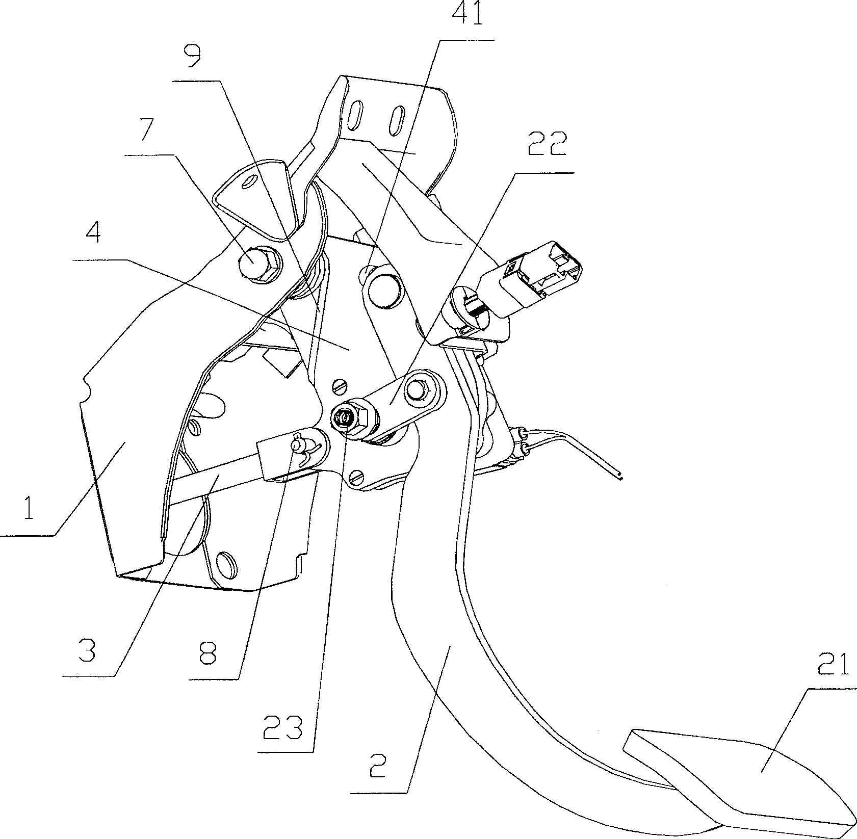
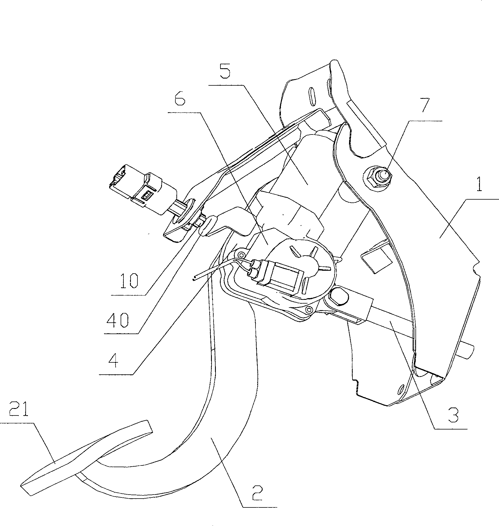
[0027] according to Figure 1 to Figure 4 As shown, the present invention includes a pedal bracket 1, a pedal strut 2, a push rod 3 and a pedal arm 4, wherein the pedal arm 4 is hinged with the pedal bracket 1, the pedal strut 2 and the push rod 3 respectively.

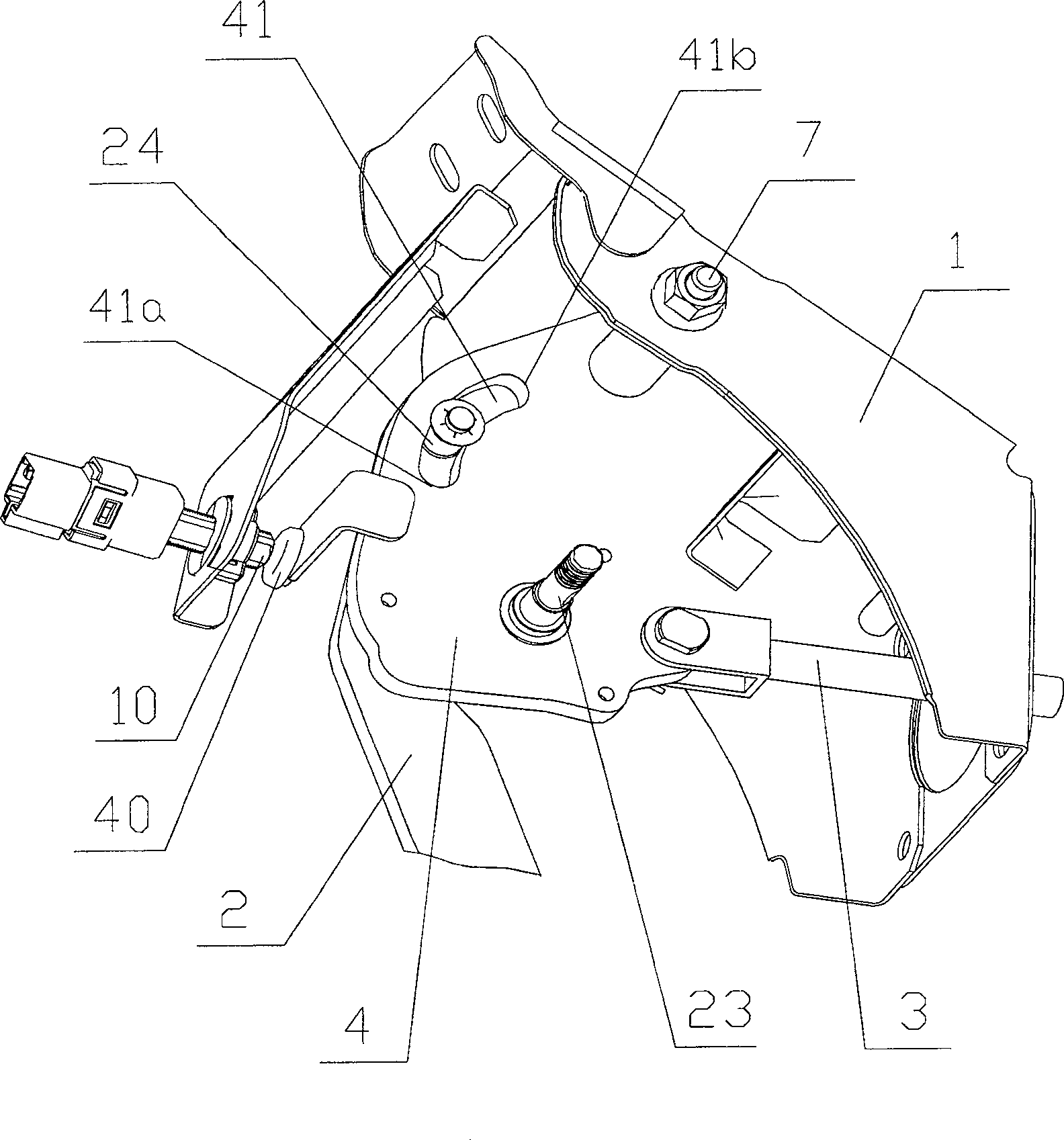
[0028] Such as figure 1 As shown, the outer end of the pedal strut 2 is connected with a pedal 21, the pedal strut 2 is hinged to the drive arm 22, and the outer end of the drive arm 22 is connected to a drive shaft 23, as Figure 4 As shown, the drive arm 22 is connected to the drive shaft 23 through a spline 25 .

[0029] Such as figure 1 and image 3 As shown, a guide groove 41 is set in the pedal arm 4, a shaft is arranged at the inner end of the pedal rod 2, and a steel sleeve 24 is attached on the shaft, and the steel sleeve 24 is clamped in the guide groove 41 and can roll in the guide ...


PUM


Abstract

An automobile pedal adjustment system related to an automobile, comprising a pedal bracket, a pedal support rod, a push rod and a pedal arm, the outer end of the pedal support rod is connected to a pedal, and the pedal arm is respectively connected to the pedal bracket, the pedal support rod and the push rod. The pedal arm is provided with a guide groove, the inner end of the pedal support rod is connected to the guide groove and the position can be adjusted, the pedal support rod is hinged to the driving arm through the spline, and the outer end of the driving arm is connected A drive shaft, the drive shaft is connected to the motor drive device through the pedal arm, the motor drive device and the drive arm are respectively installed on both sides of the pedal arm, the motor drive device includes a motor and a worm gear reducer, and the motor shaft is the same as the worm gear. The shaft is connected to each other, the upper part of the pedal bracket is also equipped with a pedal control indicator switch, the pedal arm and the pedal bracket are hinged through a support shaft, and a return spring is installed at the hinge joint, and the pedal arm is connected to the pedal bracket. The push rod is hingedly connected by a pin shaft, and the invention has good maneuverability, high safety performance and high practicability.

Description

technical field [0001] The invention relates to automobiles, in particular to an automobile pedal adjustment system. Background technique [0002] The car pedal is an important part of the vehicle control system, and its initial position in the car needs to be fully considered in the overall layout in order to obtain good control performance. [0003] The prior art automotive pedal adjustment system as described in Patent No. US6453767B1 includes a pedal bracket and a pedal strut, the outer end of the pedal strut is connected to the pedal, and also includes two pedal arms, the two pedal arms, the pedal bracket It is respectively hinged with the pedal rod, and the pedal rod is arranged between the two pedal arms and hinged by a pin shaft. There is also a driving device between the two pedal arms. The driving device includes a driving gear and a driven gear that cooperate with each other, and the driven gear A transmission shaft is arranged on the top, which matches the threa...

Claims


Application Information

Patent Timeline
Patent Type & Authority Patents(China)
IPC IPC(8): B60K26/02B60K23/02B60T7/06
Inventor 李鹏超张凯
Owner BYD CO LTD
Why Eureka
Try Eureka