
Apparatus and method for rotation speed of temperature control fan

A fan speed and fan technology, applied in temperature control, auxiliary non-electric temperature control, temperature control using electric methods, etc., can solve the problems of shortening the service life of the fan, increasing system noise, and not being included in the control system, etc., to achieve Improve reliability, prolong service life, and save energy

Inactive Publication Date: 2009-07-08
STATE GRID BEIJING ELECTRIC POWER +1
View PDF4 Cites 0 Cited by
  • Summary
  • Abstract
  • Description
  • Claims
  • Application Information

AI Technical Summary

Problems solved by technology

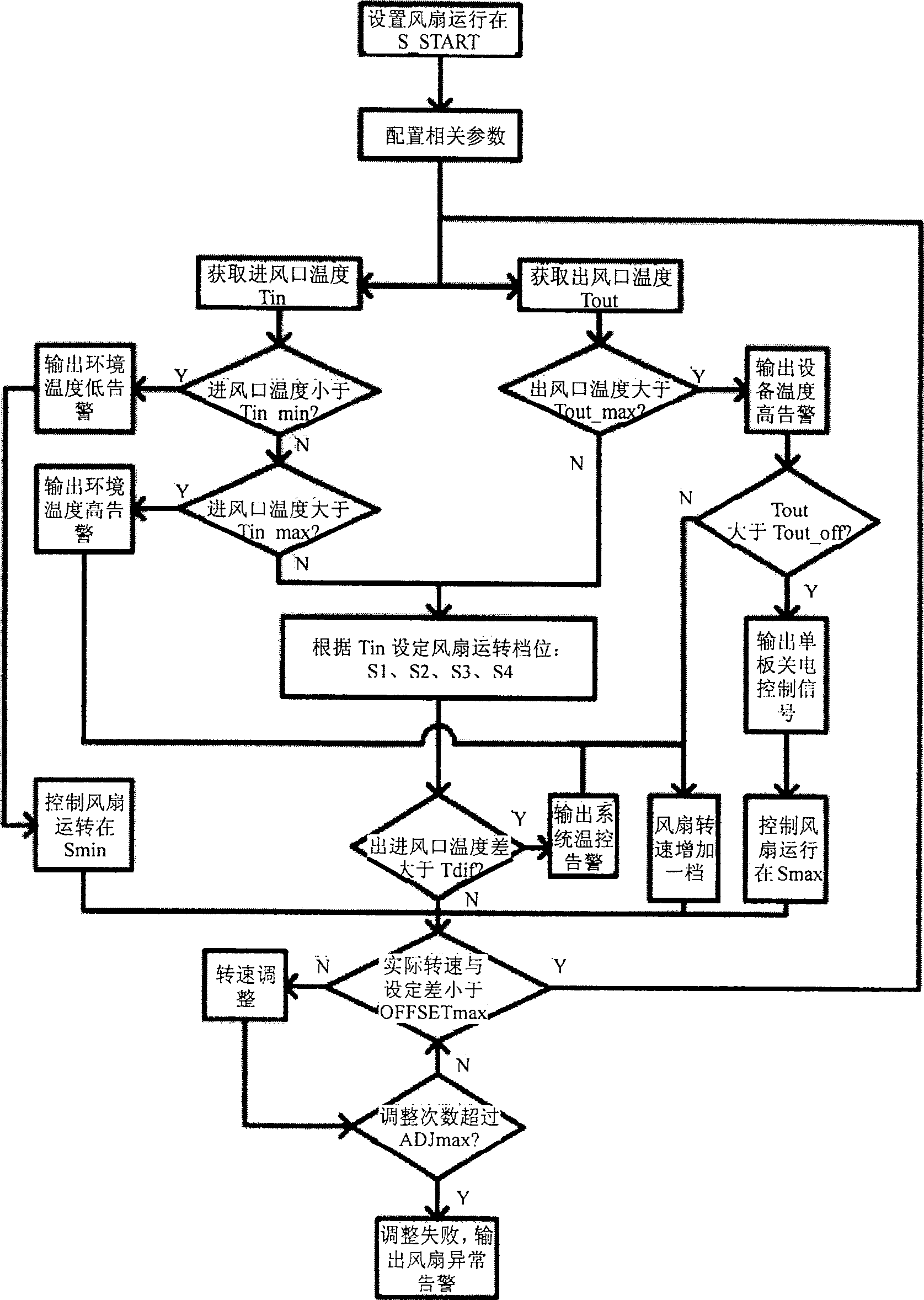
At high temperature, when there is a large difference between the actual output speed of some fans and the system setting, it will be difficult to achieve the ideal control target
And the system continues to increase the fan speed, even if the temperature of the device is finally reduced to the set value, and the price paid at this time is that other fans with no problems work at a higher speed, and if it lasts for a long time, it will increase the noise and noise of the system. Shorten the service life of the fan
[0004] At the same time, the output of the controlled object, such as fan speed and noise, is not included in the control system

Method used


Image

  • Apparatus and method for rotation speed of temperature control fan
  • Apparatus and method for rotation speed of temperature control fan
  • Apparatus and method for rotation speed of temperature control fan

Examples


Embodiment

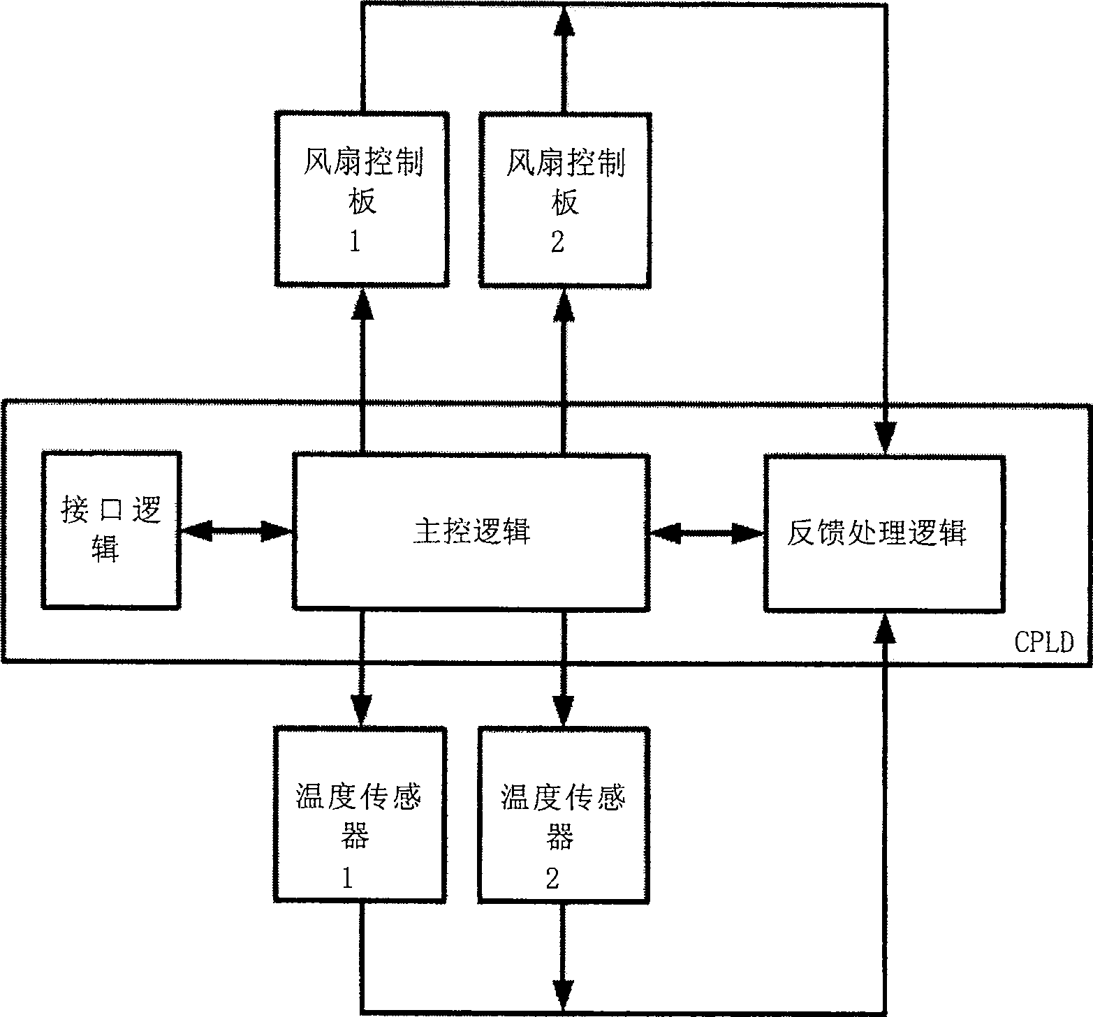
[0035] Such as figure 2 As shown, this embodiment is applied to the communication equipment in the communication room, and the CPLD (Complex Programmable Logic Device, Complex Programmable Logic Device) that realizes the main control, feedback and control interfaces is implemented on the main control single board. The main control board controls and detects the operation of the fan through the fan control board, and at the same time collects the temperature of the air inlet and outlet of the equipment through the temperature acquisition unit. Each temperature collection point has two sensors for mutual backup. In order to achieve the purpose of improving the reliability of temperature mining, when one fails, another can be used instead. The main control board can also perform power-off control on other boards. The specific implementation of the five units is described in detail as follows:

[0036] 1. The interface logic is the interface circuit between the main control log...


PUM


Abstract

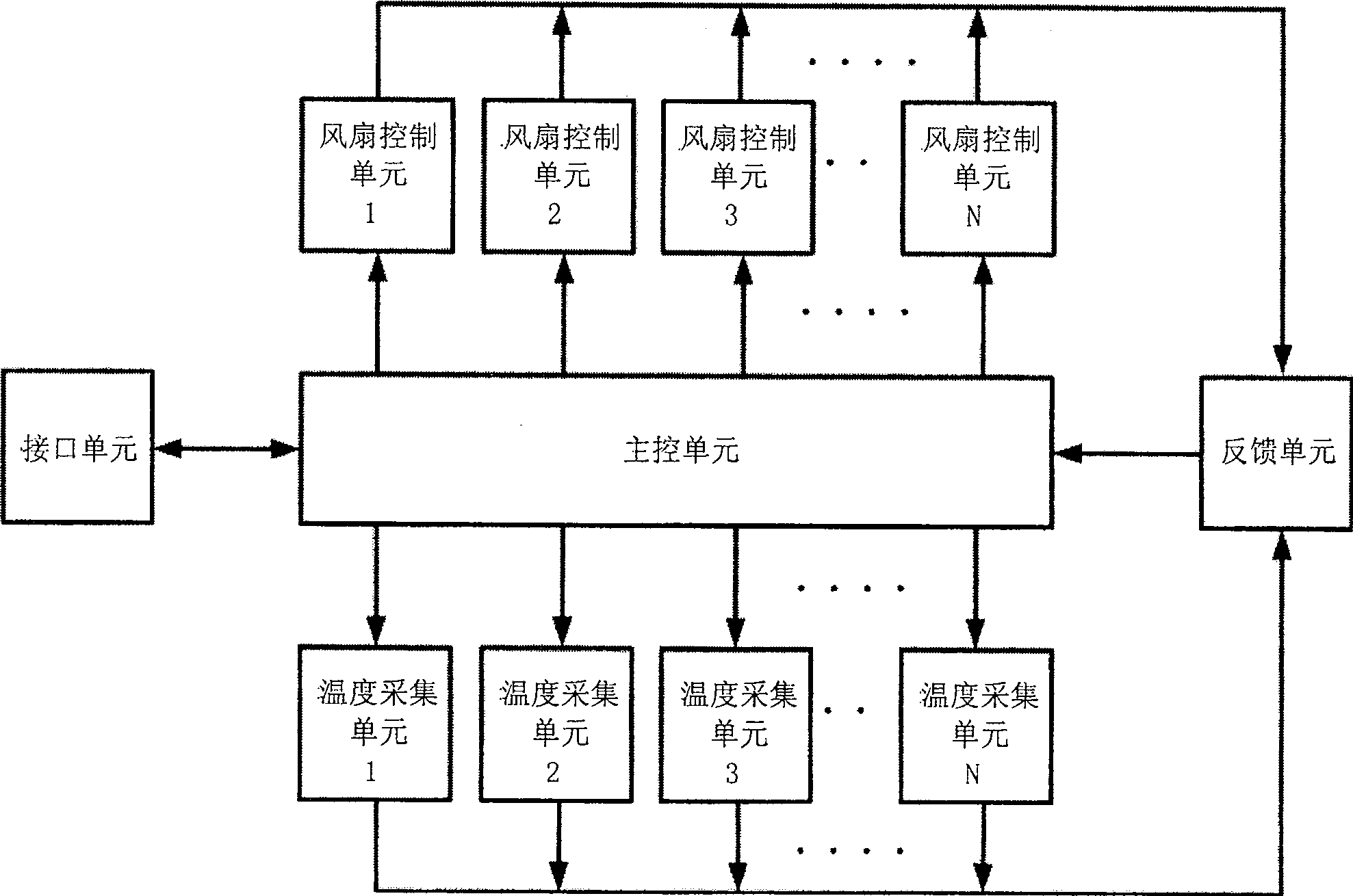
The invention discloses a device and method for temperature-controlling the speed of a fan. The device includes: an interface unit, a main control unit, a temperature acquisition unit, a fan control unit and a feedback unit; the interface unit is used to set parameters of the device from the outside Access; the main control unit obtains the optimal fan control parameters after comparison and calculation according to the parameters set by the interface unit and the fan speed and temperature parameters obtained from the feedback unit, and then controls the fan through the fan control unit; temperature collection The unit collects the temperature of the controlled device, and sends the collected temperature value to the feedback unit; the fan control unit provides the interface for the main control unit to control the fan, and sends the fan speed output signal to the feedback unit; the feedback unit sends the fan The fan speed output signal sent by the control unit and the temperature value sent by the temperature acquisition unit are processed and sent to the main control unit. The invention reduces system power consumption and improves equipment reliability.

Description

technical field [0001] The invention relates to temperature control technology, in particular to a device and method for temperature control of fan speed. Background technique [0002] At present, in the field of temperature control, air cooling is mainly used as a cooling method, and fans are used for air cooling. The current control method is to directly collect the temperature of each temperature sensing point in the system, and then adjust the fan speed according to the temperature. When the temperature rises, the fan speed is controlled to increase, and when the temperature drops, the fan speed is controlled to decrease, and so on. For example, in the existing communication room equipment, temperature sensors are placed on the boards in the equipment or wireless temperature sensors are placed in the places where the temperature needs to be measured, and then the main control board decides to control the fans to run at which file. [0003] Although this can establish ...

Claims


Application Information

Patent Timeline
Patent Type & Authority Patents(China)
IPC IPC(8): G05D23/19G05D23/185G05D23/20
Inventor 熊丹郭俊敏喻晓钟赛飞
Owner STATE GRID BEIJING ELECTRIC POWER
Learn More