Oppositely clamped type direct-acting valve

一种直动阀、夹式的技术,应用在升阀、阀细节、安全阀等方向,能够解决制造成本增加、笨重等问题,达到制造成本降低、总体重量减轻、负荷降低的效果

Active Publication Date: 2009-07-15
KANE KOUGYOU
View PDF9 Cites 0 Cited by
  • Summary
  • Abstract
  • Description
  • Claims
  • Application Information

AI Technical Summary

Problems solved by technology

[0006] However, if the valve box is formed with a flange, such as in the case of a flange-type direct acting valve, some problems arise, so that not only the valve itself will become heavy, but also the manufacturing cost of the valve will be high due to the high cost of the flange itself. material cost increases

Method used


Image

  • Oppositely clamped type direct-acting valve
  • Oppositely clamped type direct-acting valve
  • Oppositely clamped type direct-acting valve

Examples


Embodiment Construction

[0019] Next, an example as an embodiment of the present invention will be described based on the drawings.

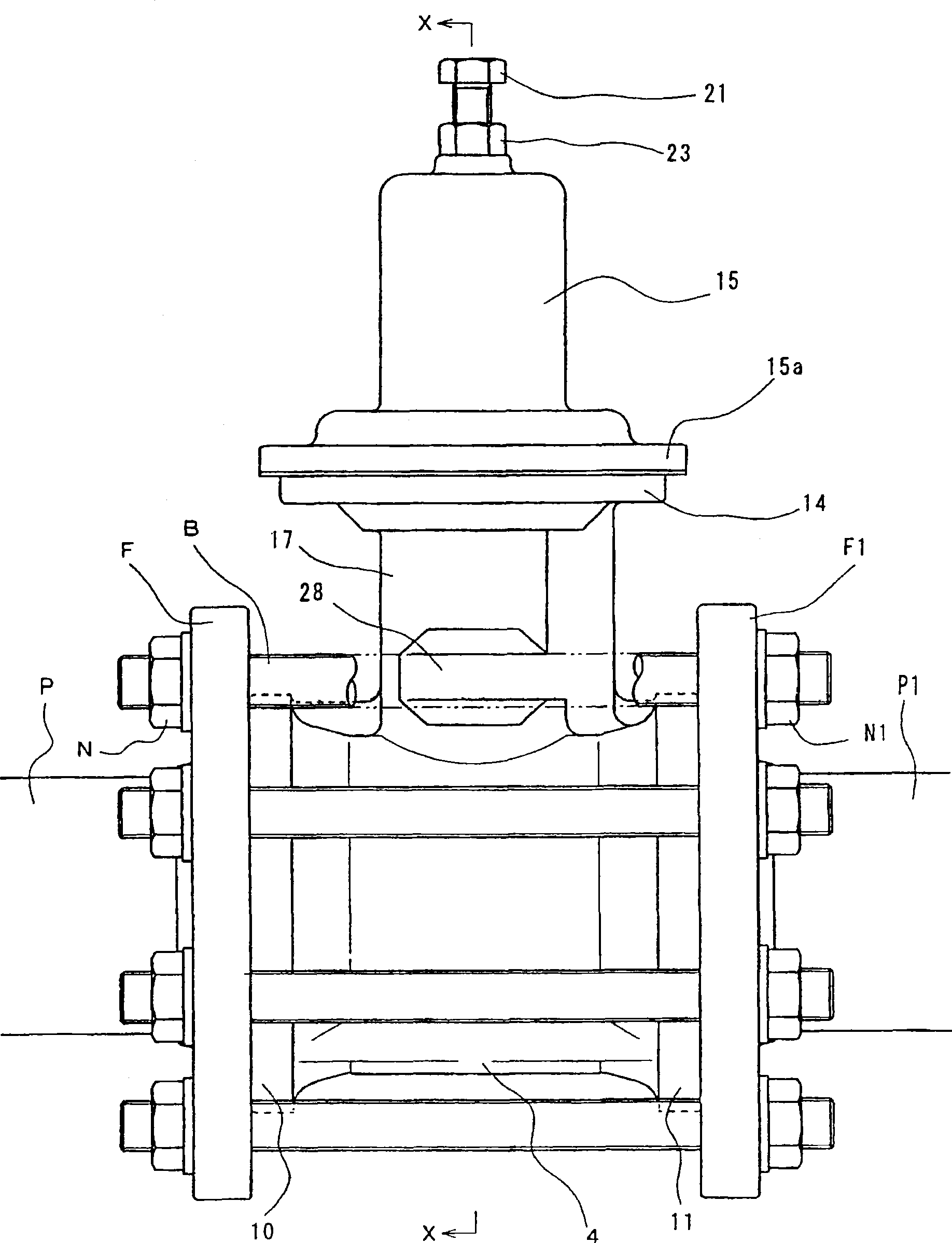
[0020] figure 1 It is a front view of the piping state of the wafer type direct acting valve.

[0021] figure 2 for along figure 1 The cross-sectional view cut by the XX-X line.

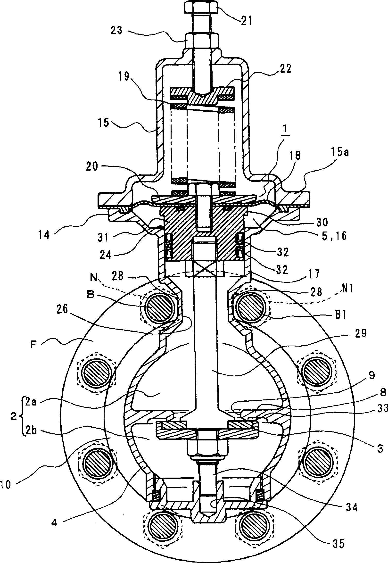
[0022] image 3 for along figure 1 Longitudinal cross-sectional view taken along the XX-X line.

[0023] Figure 4 for the partially omitted along image 3 The enlarged cross-sectional view cut by the Y—Y line of .

[0024] The valve is a direct-acting valve, which includes a driving part 1 that operates when primary pressure or secondary pressure is detected, and a valve body 3 that communicates with (or is connected to) the driving part 1 and is manipulated to open and close flow path 2. The valve shown is a direct acting pressure reducing valve.

[0025] The structure of the direct acting pressure reducing valve is as follows. The valve box (or valve chamber) 4 includes the flo...


PUM


Abstract

In the direct acting valve of the present invention, no flange is formed in the valve box, and the pipe connection is realized by inserting the valve box between the pipe flanges. The direct acting valve of the present invention includes: a driving part (1) operated by detecting a primary pressure or a secondary pressure; and a valve body (3) communicating with the driving part (1) to open and close a flow path (2). The valve box (4) of the valve is clamped between pipe flanges (F and F1 ) fastened by bolts (B, B1 . . . ) and nuts (N, N1 . . . ). The connection ends (10 and 11) respectively having the inlet (6) and the outlet (7) of the flow path (2) and mating with the pipe flanges (F and F1) are made into a flangeless structure. A cover flange neck (17) extends upwardly from the valve box (4) and is formed to be inserted between bolts (B and B1 ) located between the pipe flanges (F and F1 ) between and adjacent to each other on the periphery of the pipe flanges (F and F1).

Description

technical field [0001] The present invention relates to a wafer-type direct-acting valve in which direct-acting valves such as pressure regulating valves (such as pressure reducing valves), solenoid valves, and constant water level valves are clamped between pipe flanges and bolts through the pipe flange and the like. Background technique [0002] Conventionally, there is a wafer type valve in which the valve box is located between pipe flanges, and the pipe flanges are fastened by bolts and nuts. As this type of valve, there are single plate check valves and flangeless butterfly valves. In these valves, a thin disc-shaped valve body oscillates or rotates within a thin cylindrical valve box, opening and closing a flow path through which fluid flows linearly. These valves are relatively simple in structure and operation (for example, see Non-Patent Document 1). [0003] On the other hand, there are also direct acting valves in which the valve body is connected to the drive...

Claims


Application Information

Patent Timeline
Patent Type & Authority Patents(China)
IPC IPC(8): F16K17/02G05D16/06F16K1/00F16K27/00F16K31/122
CPCY10T137/7825Y10T137/7504F16K41/12F16K27/08F16K17/06F16K27/0236
Inventor 落合优山口寿之
Owner KANE KOUGYOU
Why Eureka
Try Eureka