Cutter

A technology for cutting machines and cutting knives, which is applied in the direction of shearing devices, mechanical equipment, metal sawing equipment, etc. It can solve the problems of no tension adjustment, no deceleration function, and the transmission unit cannot transmit rotational force, etc., to achieve reduction The effect of failure rate, low repair cost and good appearance

Inactive Publication Date: 2009-07-22
崔二九
View PDF8 Cites 0 Cited by
  • Summary
  • Abstract
  • Description
  • Claims
  • Application Information

AI Technical Summary

Problems solved by technology

[0014] However, although the transmission part of the circular saw machine of the above structure is a two-stage transmission, the transmission wheel in the middle, that is, the first driven wheel coaxial with the first driven shaft, does not have a variable diameter design, does not have a deceleration function, and only plays a role in reducing the speed. In addition, the first driven wheel does not have a tension adjustment function, so that the transmission unit cannot transmit stable rotational force

Method used


Image

  • Cutter
  • Cutter
  • Cutter

Examples


Embodiment Construction

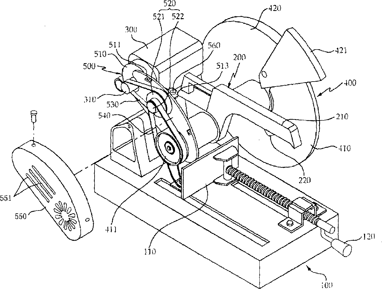
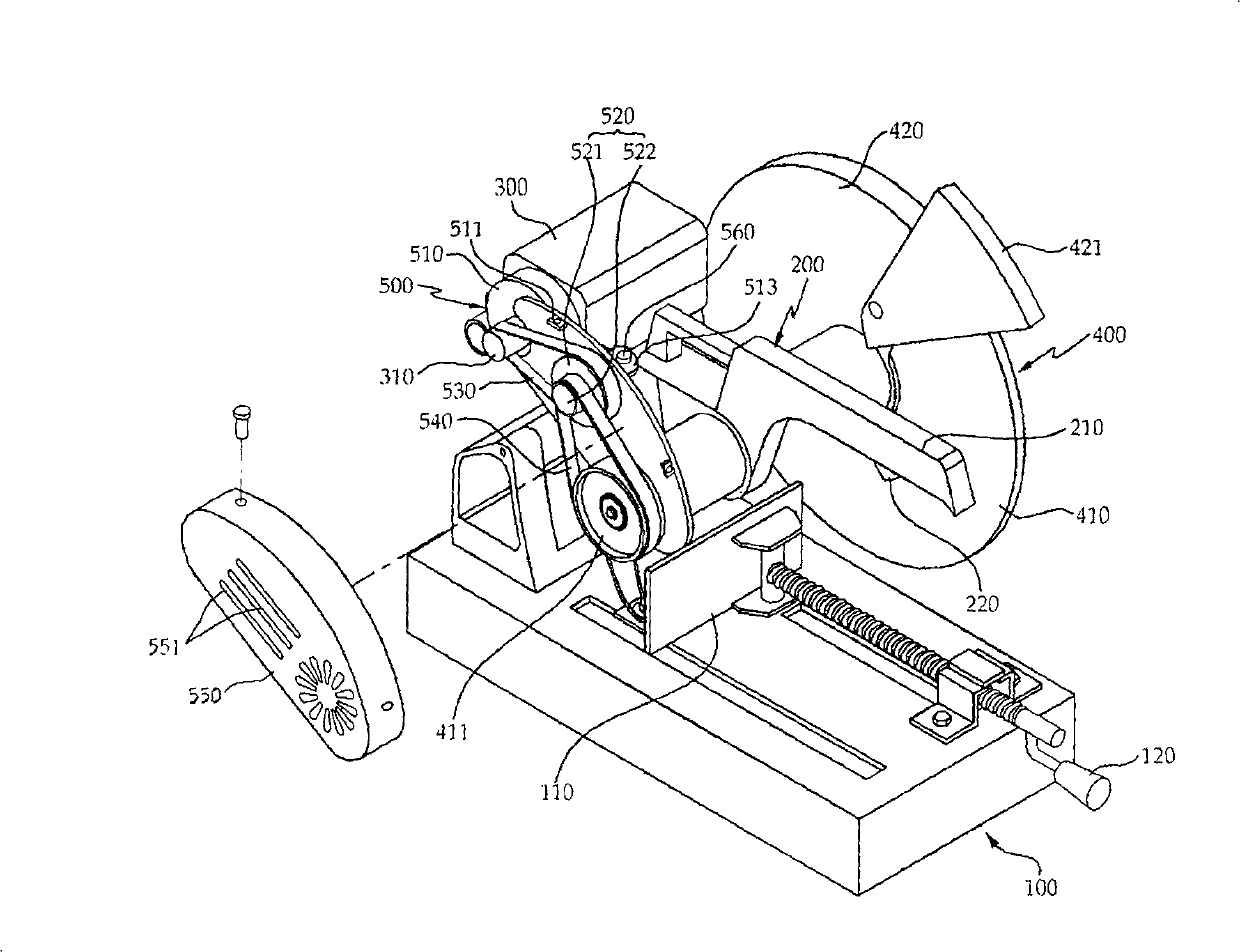
[0051]Below, refer to the attached Figure 2 to Figure 7 , the ideal embodiment of the present invention will be described in detail.

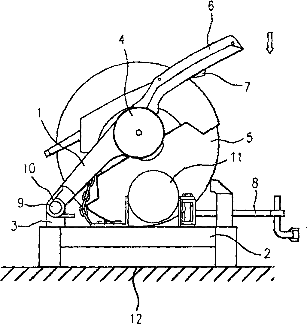
[0052] Such as Figure 2 to Figure 4 As shown, the cutting machine of the present invention cuts hard metal through a cutting knife rotating at a high speed, and it includes: an operating table 100 arranged on the ground; a frame 200, one end of which is rotatably fixed on the above-mentioned operating table 100, The other end is provided with a switch; the motor 300 is arranged on one end of the above-mentioned frame 200; the cutting part 400 is arranged on the side of the above-mentioned frame 200, and is provided with a cutting knife; the transmission part 500 connects the above-mentioned motor 300 and the cutting knife.

[0053] The above-mentioned console 100 is used to place workpieces, one end of which is rotatably hinged with a frame 200, on which a vise 110 is arranged, the above-mentioned vise can be moved back and forth by the rot...


PUM

PropertyMeasurementUnit
diameteraaaaaaaaaa

Abstract

The present invention relates to a cutter, which includes an operating bench (100); a machine frame (200), which is rotatablely fixed on the operating bench by one end, and a switch is provided on the other end; a motor (300), which is mounted at one end of the machine frame; a cutting part (400), which is positioned at one side of the machine frame and is provided with a cutting blade (410); a transmission part (500), which transfers the power of motor to the cutting blade through a belt. The transmission part comprises: a fixing plate, which is mounted on one side of the machine frame, and on which a rotation shaft for the motor and a rotation shaft for the cutting blade are provided projecting on the side portion of the machine frame; a reduction pulley (520), which is rotatablely mounted on the fixing plate and has a two step structure; a first belt a second belt for joining the driving pulley on the motor rotation shaft and the major diameter pulley of the reduction pulley and joining the minor diameter pulley of the reduction pulley and the driven pulley on the rotation shaft of the cutting blade. The present invention can provide a optimum rotary speed required for cutting a workpiece, significantly reduce the noise, and since no gear is used, the failure rate is significantly reduced, it is convenient for maintenance and the maintenance costs is lowered.

Description

technical field [0001] The invention relates to a cutting machine, especially a cutting machine that transmits power to a motor and a rotary cutting knife through a belt connection, so that a more stable rotating force can be transmitted and the maintenance is easy. Background technique [0002] Usually, the cutting machine cuts hard metal by its high-speed rotating cutting knife, such as figure 1 As shown, it includes: a cutting part, which is provided with a device for cutting the workpiece; a base part, which fixes the workpiece and provides support for the cutting part; a coupling part, which connects the above-mentioned base part and the cutting part. [0003] Specifically, the above-mentioned cutting part includes: a frame 1; a motor 4 installed on one side of the above-mentioned frame 1 to generate a driving force; arranged on the above-mentioned frame 1 and rotated by the driving force of the above-mentioned motor 4 to cut the workpiece The cutting knife 5 of 11; in...

Claims


Application Information

Patent Timeline
Patent Type & Authority Patents(China)
IPC IPC(8): B23D17/02B23D33/00F16H7/02F16H7/08B26D5/08B26D1/14B26D7/00
CPCB23D47/12Y10T83/7793B23D45/042
Inventor 崔二九
Owner 崔二九
Why Eureka
Try Eureka