Combination method mounting technique for ultra-large type steel converter

A steel-making converter and combined installation technology, which is applied in assembly machines, manufacturing converters, metal processing equipment, etc., can solve the problems of large engineering investment, installation of transmission devices that cannot be steel-making converters, and large volume.

Active Publication Date: 2009-08-12
中国冶金科工股份有限公司
View PDF5 Cites 0 Cited by
  • Summary
  • Abstract
  • Description
  • Claims
  • Application Information

AI Technical Summary

Problems solved by technology

[0002] Due to the large size and heavy weight of large or super-large steelmaking converters, which can weigh hundreds of tons or even nearly a thousand tons after assembly, the steelmaking span cannot be directly hoisted in place by crane. At present, the installation of large or super large steelmaking converters at home and abroad is generally Use the "slip method" or "trolley method" for installation; slip method: when assembling, use a large bridge crane on the feeding span to move the three major parts of the converter body: the support ring and the bearing seat, the furnace shell and the converter The transmission device is assembled into a whole, and then the whole slides to the installation position of the steelmaking span. The converter is installed by the sliding method in the Shanghai Baosteel stainless steel steelmaking project, but the steel column foundation, steel columns and steel beams of the operating platform in front of the furnace must be To increase the design load, the design of the bearing base must be changed, increasing the project investment, and there are safety risks. Therefore, the installation of large or super-large steelmaking converters by sliding method requires large project investment and safety risks; The installation of steel converters generally adopts the ladle trolley method, that is, a supporting platform is set up on the ladle trolley, but only the two major parts of the assembled converter body: the support ring, the bearing seat and the furnace shell can be moved to the installation position as a whole. The stability is poor when moving, and the transmission device of the steelmaking converter cannot be installed in place at the same time

Method used


Image

  • Combination method mounting technique for ultra-large type steel converter
  • Combination method mounting technique for ultra-large type steel converter
  • Combination method mounting technique for ultra-large type steel converter

Examples


Embodiment

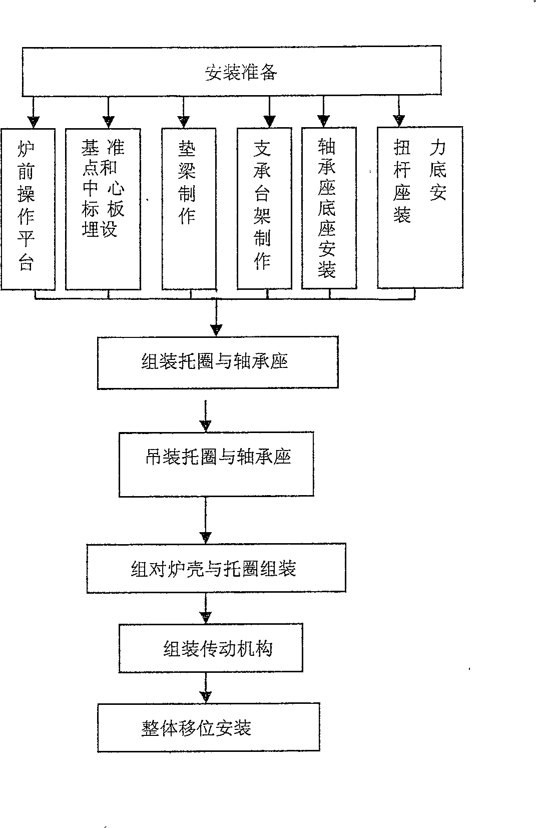
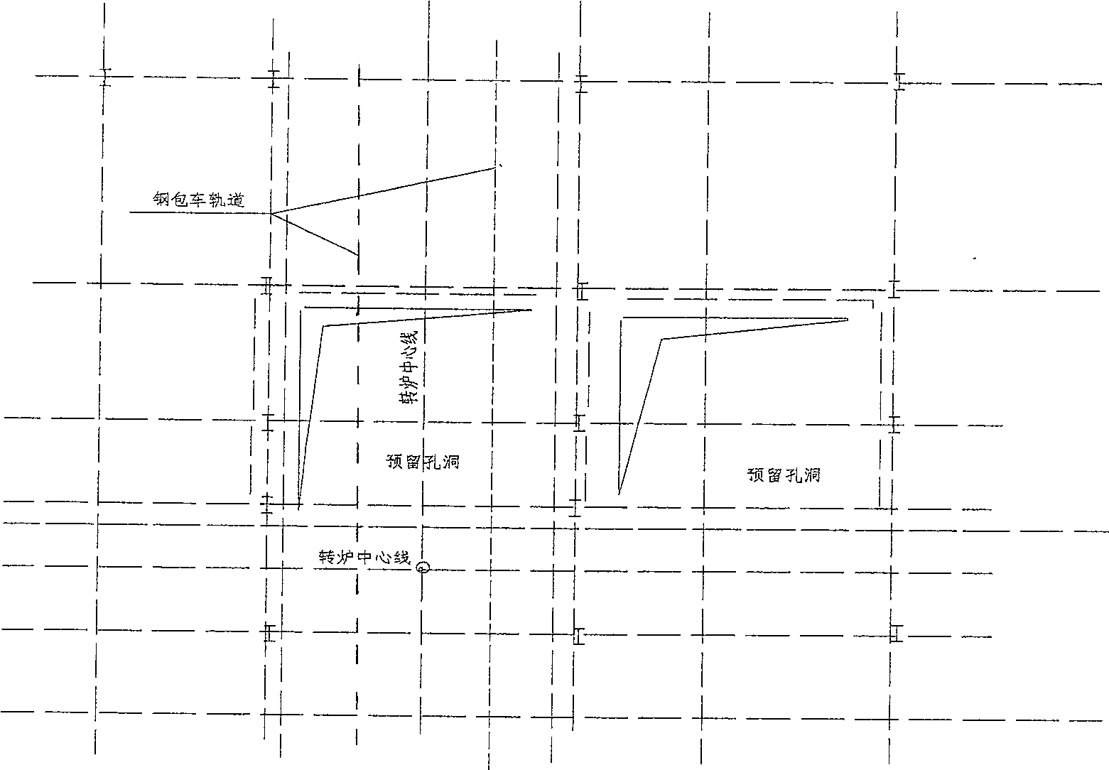
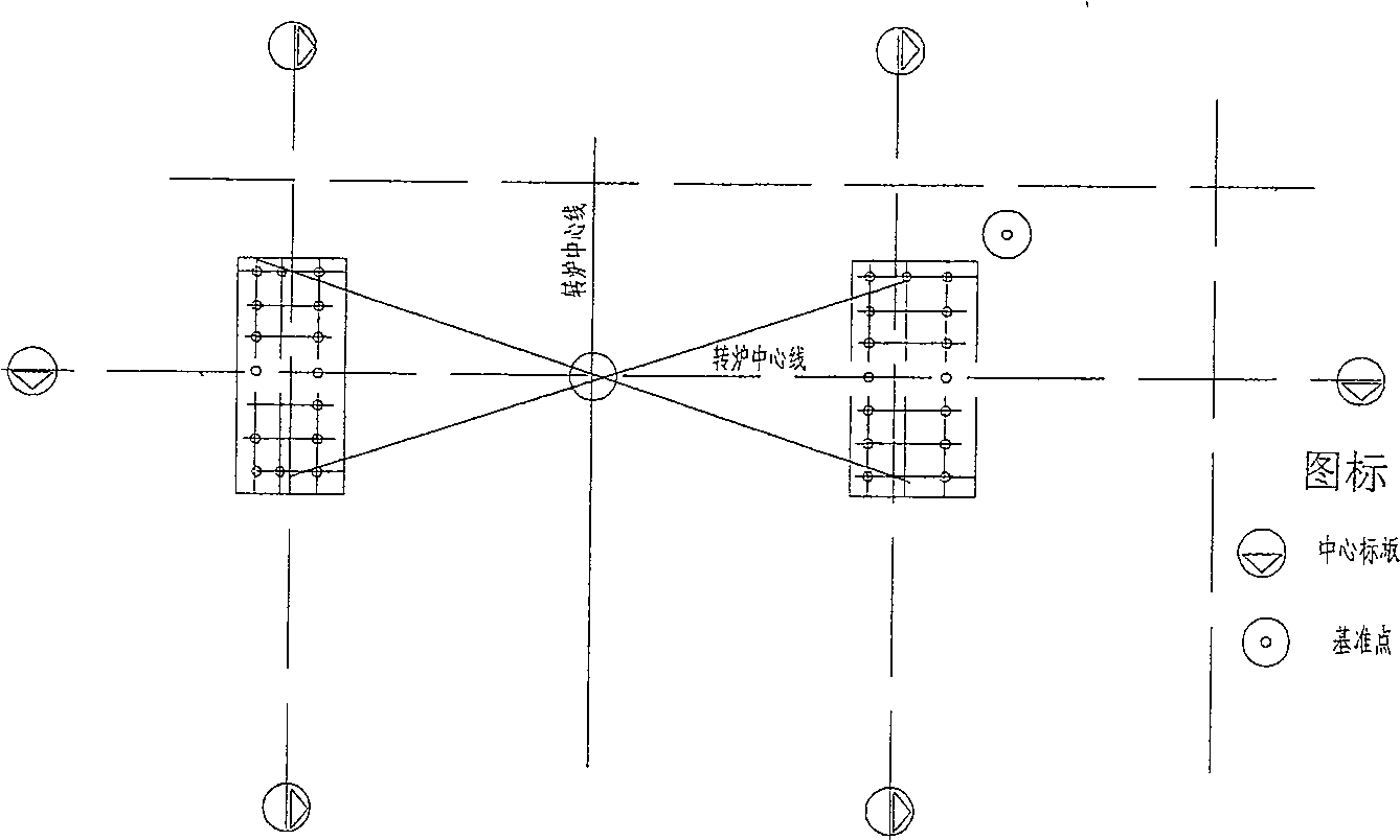
[0074] Example: Two 300t converters in Maanshan Iron and Steel New District, which were constructed by China No. 17 Metallurgical Construction Co., Ltd., were installed by combined installation method during construction. In the feeding span workshop with large bridge cranes, three converters were installed: Support ring and bearing seat: 302t, furnace shell and "voestalpine" Con Link three-point suspension device: 260t and transmission mechanism: 130t, assembled into a whole converter with a total weight of 692t; On the pad beam of the roller bar; the trolley, that is, the molten steel tanker, is towed by a 5t hoist and a 30t main pulley block for moving, and a 10t single pulley block and the main hook of the steelmaking straddle bridge are used for traction at the drive side bearing seat, and are jointly pulled to the installation position of the steelmaking straddle converter. The converter is installed in place as a whole.

[0075] The first converter began to move from th...


PUM


Abstract

The present invention is a combined installation method of a super-large steelmaking converter, which belongs to the installation of steelmaking equipment. At the base of the bearing seat on the side and the non-drive side, a pad beam is installed on the steel column or steel beam of the operating platform in front of the furnace. The three major parts are hoisted to the hydraulic press supporting the platform and the pad beam equipped with roller bars and assembled into a whole. The hydraulic press is adjusted to balance the force on each supporting point. The hoist and The main pulley group pulls the molten steel tank car and the supporting platform on it. A single pulley is set at the bearing seat on the transmission side. The main hook of the steelmaking span is used for traction, and the direction is corrected by adjusting the roller bars. In the installation position, it is safe and reliable, with high efficacy and strong operability.

Description

technical field [0001] The invention belongs to the installation of steelmaking equipment, in particular to the installation of a large or super large steelmaking converter. Background technique [0002] Due to the large size and heavy weight of large or super-large steelmaking converters, which can weigh hundreds of tons or even nearly a thousand tons after assembly, the steelmaking span cannot be directly hoisted in place by crane. At present, the installation of large or super large steelmaking converters at home and abroad is generally Use the "slip method" or "trolley method" for installation; slip method: when assembling, use a large bridge crane on the feeding span to move the three major parts of the converter body: the support ring and the bearing seat, the furnace shell and the converter The transmission device is assembled into a whole, and then the whole slides to the installation position of the steelmaking span. The converter is installed by the sliding method ...

Claims


Application Information

Patent Timeline
Patent Type & Authority Patents(China)
IPC IPC(8): B23P21/00C21C5/28
Inventor 胡明德李中元史朝华施光涛刘少美吴强
Owner 中国冶金科工股份有限公司
Why Eureka
Try Eureka