Electronic sensing type electric pressure cooker

An electric pressure cooker and sensing technology, applied in pressure cookers and other directions, can solve the problems affecting the safety and reliability of the electric pressure cooker, the pressure adjustment deviates from the set value, and the control accuracy is not high, and achieves simple structure, reliable performance, and control range. wide effect

Inactive Publication Date: 2009-09-02
李寿民 +1
View PDF6 Cites 62 Cited by
  • Summary
  • Abstract
  • Description
  • Claims
  • Application Information

AI Technical Summary

Problems solved by technology

[0004] The disadvantage of the above structure is that the control accuracy is not high because the flashing switch works with contacts, and it often occurs that the actual pressure adjustment in the pot deviates from the set value or even falls due to fatigue, oxidation, deformation, corrosion and burnt contacts. Out of control, affecting the safety and reliability of the electric pressure cooker, bringing potential danger to consumers

Method used


Image

  • Electronic sensing type electric pressure cooker
  • Electronic sensing type electric pressure cooker

Examples


Embodiment 1

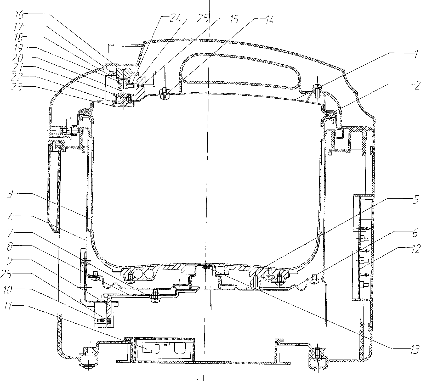
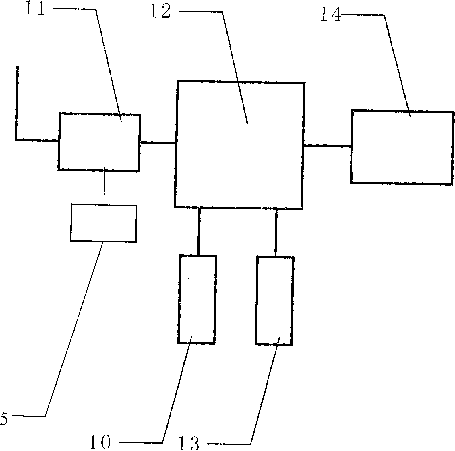
[0023] The induction source assembly and the sensor 10 are arranged at the bottom of the inner pot 3 . The induction source assembly is composed of a moving part 9 attached with a magnetic source or light source 25 , the moving part 9 is connected with the elastic ring 6 through the adjusting piece 8 and moves up and down with the deformation of the elastic ring 6 . The sensor 10 is a stroke sensor, which is located on one side of the induction source assembly. The control chip 12 can adopt the S3F9454 chip produced by South Korea's Samsung Electronics.

[0024] When the pressure inside the pot increases, the pot inner 3 presses down on the elastic ring 6 to make it deform, thereby driving the moving part 9 to move down to the set position, reaching the sensing distance of the sensor 10, and the sensor 10 can sense the light at this time Or magnetically, an induction signal is sent to the control chip 12, and the control chip 12 sends an instruction to cut off the power suppl...

Embodiment 2

[0028] In the conjoined pot cover structure, the induction source assembly and the sensor 15 can be arranged inside the pot cover 1 . The induction source assembly is composed of a moving part 24 with a magnetic source or a light source 25 attached, and the moving part 24 is connected and linked with the pressure valve of the pot cover 1 . The pressure valve includes a pressure regulating screw 16, a locking nut 17, a sensor bracket 18, a pressure regulating spring 19, a valve core 20, a valve cap 21, a valve seat 22 and a rubber sleeve 23 and the like. The moving part 24 is arranged on the valve core 20 and moves up and down with the valve core. The valve core 20 and the moving part 24 can be made integrally or separately.

[0029] The pressure regulating screw 16 is used to adjust the working pressure value of the pressure regulating spring 19. When the pressure in the pot rises, the valve core 20 is pushed up by the soft rubber sleeve 23 to move upward, so that the moving ...

Embodiment 3

[0032] In order to further improve safety, the automatic pressure control mechanism includes two sets of induction source components and inductors, which are respectively arranged at the bottom of the pot liner 3 (as in embodiment 1) and inside the pot cover 1 (as in embodiment 2).

[0033] Similarly, a bottom temperature sensor 13 is also provided at the bottom of the pressure cooker pot 3 , and a pot cover temperature sensor 14 is provided on the pot cover 1 .


PUM


Abstract

The invention discloses an electronic sensor type electric pressure cooker, which comprises a pot cover, a power supply board, a heating plate and an automatic pressure control mechanism. The sensor on the side, and the control chip connected between the sensor and the heating plate; the sensor sends an induction signal to the control chip, and the control chip sends an instruction to turn on or cut off the power supply of the heating plate. The invention uses electronic sensing to control the internal pressure of the inner pot, and the whole control process is non-contact controlled, with simple structure, reliable performance, wide control range, high precision, high sensitivity, and the safety performance is much better than that of the electric pressure cooker using the traditional control mechanism. .

Description

technical field [0001] The invention relates to an electric pressure cooker, in particular to an electronic sensor type electric pressure cooker. Background technique [0002] The electric pressure cooker on the existing market all adopts flashing switch (also known as: sensitive switch) to turn on or cut off the power supply of heating plate, thereby realizes that pressure is adjusted and controlled. [0003] For example, a kind of electric pressure cooker disclosed in Chinese patent 91100026.7, its pressure automatic control mechanism includes the elastic arm that laterally compresses the bottom of the pot body, the displacement transmission part that is arranged on the elastic arm and the flashing switch that is arranged at the bottom of the elastic arm, flashing The switch and the power supply are connected into a series circuit, and the pressure in the pot causes the elastic arm to move downward to drive the flashing switch to control the heating state of the electric h...

Claims


Application Information

Patent Timeline
Patent Type & Authority Patents(China)
IPC IPC(8): A47J27/08
Inventor 李寿民
Owner 李寿民
Why Eureka
Try Eureka