Transistor tube valve with force top pressing structure

A thyristor valve and thyristor technology, which is applied to electrical components, electro-solid devices, circuits, etc., can solve the problems of laborious installation and maintenance, high strength requirements of top-loading bolts, etc., to achieve simple structure, improve operation safety, and reduce strength requirements Effect

Active Publication Date: 2009-09-09
CHINA ELECTRIC POWER RES INST +1
View PDF4 Cites 0 Cited by
  • Summary
  • Abstract
  • Description
  • Claims
  • Application Information

AI Technical Summary

Problems solved by technology

At present, there is no such device in China. The structure of other similar devices is that a single bolt presses in the center, and the top pressure is borne by one bolt. The installation and maintenance are laborious and the strength of the top pressure bolt is high.

Method used


Image

  • Transistor tube valve with force top pressing structure
  • Transistor tube valve with force top pressing structure
  • Transistor tube valve with force top pressing structure

Examples


Embodiment Construction

[0013] The present invention will be described in detail below in conjunction with the accompanying drawings and embodiments.

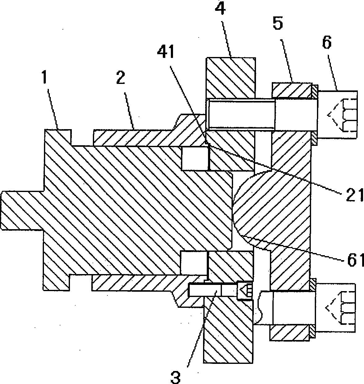
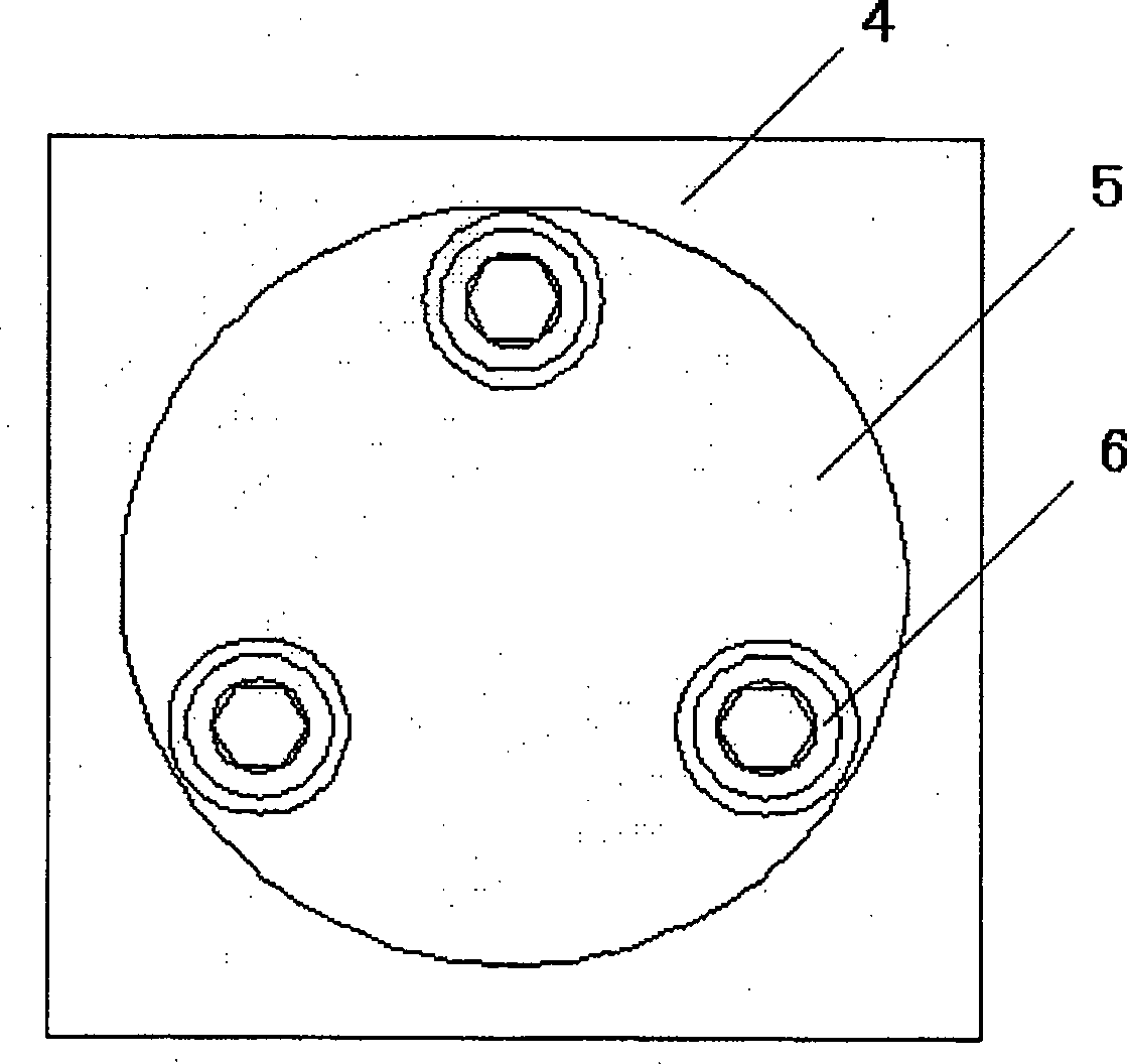
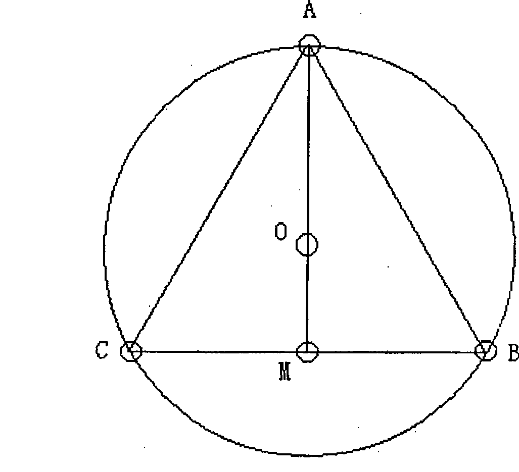
[0014] Such as figure 1 As shown, the present invention includes a pressing guide rod 1, and a guide sleeve 2 is set on the pressing guide rod 1. There is a clearance fit between the pressing guide rod 1 and the guide sleeve 2, so that the pressing guide rod 1 can be guided along the The sleeve 2 slides axially and keeps them concentric. One end of the guide sleeve 2 is connected to the flange 4 through the screw 3, and the guide sleeve 2 and the flange 4 are positioned through the seams 21 and 41 and also kept concentric. The flange plate 4 is connected to a pressure plate 5 through three pressure bolts 6. The end of the pressure plate 5 in contact with the pressure guide rod 1 is a spherical head 61. The pressure plate 5 is connected to the pressure plate 5 through three pressure bolts 6. On the flange 4, the spherical head 61 of the pressing plate...


PUM


Abstract

The invention relates to a thyristor valve with a component force jacking mechanism, and the invention comprises a thyristor valve string which is composed of a plurality of thyristors and radiators which are in interval distribution, a disc spring and a flange disk which are arranged at one end of the thyristor valve string, a disc spring guide rod which is connected on the flange disk and a jacking device which is arranged at the other end of the thyristor valves string. The invention is characterized in that the jack mechanism is the component force jacking mechanism and comprises a jacking guide rod. The outer part of the jacking guide rod is provided with a guide sleeve, and the end part of which is connected with a flange disk by screws. The end part of the flange disk is connected with a jacking plate by three jacking bolts. One end where the jacking guide rod touches the jacking plate is a ball head. The flange disk on the component force jacking mechanism and the flange disk at one side of the disc spring are connected with an upper fixed plate and a lower fixed plate via bolts. The invention has the advantages of simple structure, convenient installation and repair, safe use, broad application in a controllable series compensation device and a static compensation device in the power system.

Description

technical field [0001] The invention relates to a thyristor valve, in particular to a thyristor valve with a component force pressing mechanism. Background technique [0002] The thyristor valve is the core component of the controllable series compensation device and the static compensation device of the power system. With the continuous development of power electronics technology, the thyristor as the core component is getting larger and larger, and the mechanical pressure required for its work is also increasing. When it is installed, it is required to keep the table of the thyristor parallel and concentric with the table of the radiator; during the installation process, it is required to apply pressure through the centerline of the component so that the pressure is evenly distributed in the entire contact area; the pressure must meet the required requirements , so it is necessary to provide a thyristor component force pressing mechanism that can meet the above requiremen...

Claims


Application Information

Patent Timeline
Patent Type & Authority Patents(China)
IPC IPC(8): H01L25/00H01L25/07
Inventor 李志麒常忠王承民左永仁
Owner CHINA ELECTRIC POWER RES INST
Why Eureka
Try Eureka