

Small DC motor
A DC motor, small technology, applied in the direction of DC commutator, electrical components, electromechanical devices, etc., can solve the problems of the reduction of the effective magnetic flux of the armature core and the inability to exert the torque effectively, and achieve the expansion and reduction of the winding space. Size, effect of increasing torque
- Summary
- Abstract
- Description
- Claims
- Application Information
AI Technical Summary
Problems solved by technology
Method used
Image

Examples
Embodiment approach 1
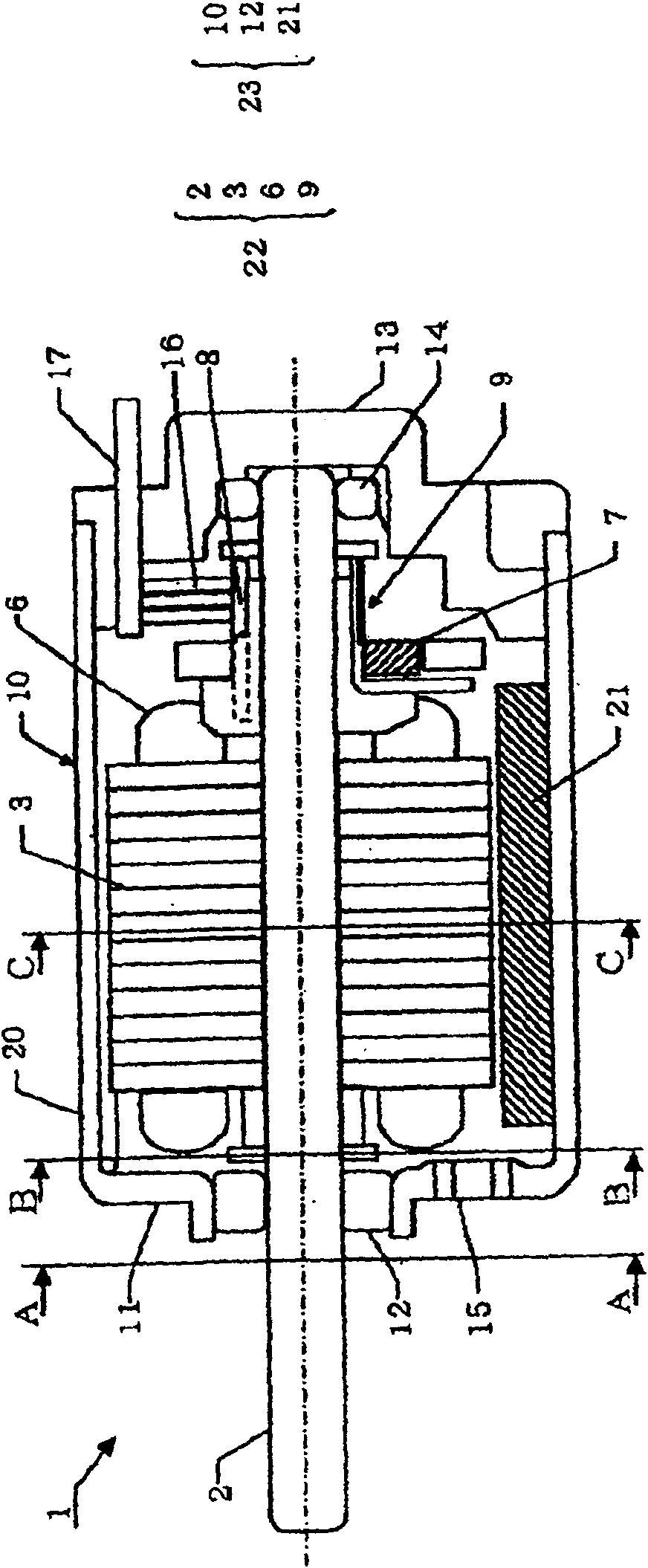
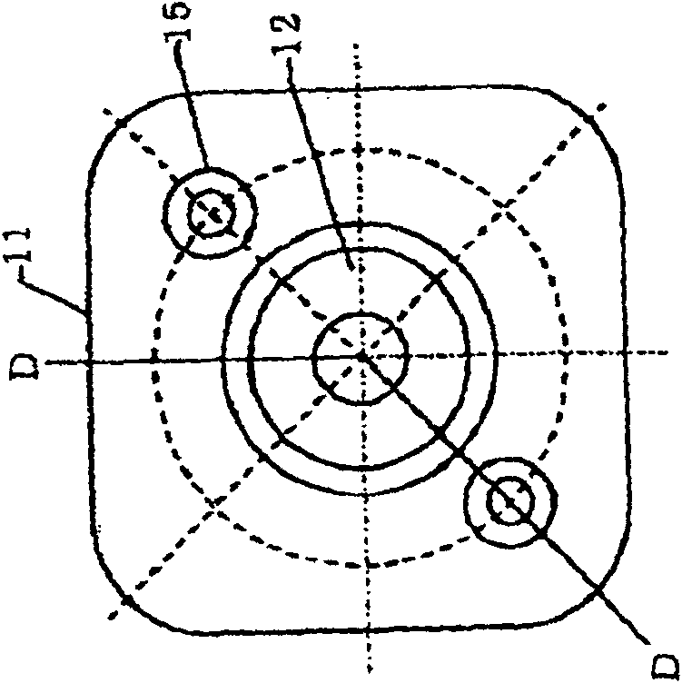
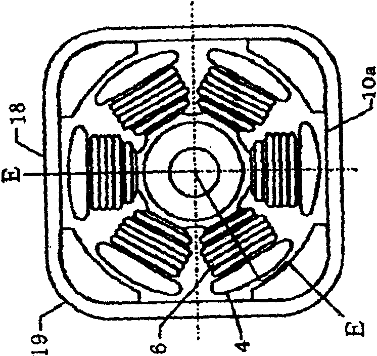
[0049] Figure 1A to Figure 1D is a configuration diagram illustrating a small DC motor according to Embodiment 1 of the present invention. In Embodiment 1, the case where the armature assembly has the armature core is described.
[0050] Figure 1A is a longitudinal cross-sectional view along the axis of rotation, and, at Figure 1A , the part from line A-A to line B-B is Figure 1B In the cross-sectional view of line D-D, the part from line B-B to line C-C is Figure 1C The sectional view of line E-E in middle, and the part from line C-C to the end block is Figure 1D The cross-sectional view of the F-F line in the middle. Figure 1B yes Figure 1A The cross-sectional view of the A-A line in the middle, Figure 1C yes Figure 1A The sectional view of the B-B line in the middle, and Figure 1D is Figure 1A The cross-sectional view of the C-C line in the middle.
[0051] exist Figure 1A The small DC motor 1 shown in has an armature assembly 22 and a housing assem...
Embodiment approach 2
[0072] Figure 2A to Figure 2D is a configuration diagram illustrating a small DC motor according to another embodiment of the present invention.
[0073] Figure 2A is the longitudinal section view of the shaft, and, at Figure 2A In, the part from H-H line to I-I line is Figure 2B In the cross-sectional view of the K-K line, the part from the I-I line to the J-J line is Figure 2C The sectional view of the L-L line in the middle, and the part from the J-J line to the end block is Figure 2D The cross-sectional view of the M-M line in the middle.
[0074] Figure 2B yes Figure 2A The cross-sectional view of the H-H line in the middle, Figure 2C yes Figure 2A The cross-sectional view of the I-I line, while Figure 2D is Figure 2A The cross-sectional view of J-J line in the middle.
[0075] FIG. 2 has the same constituent elements as FIG. 1 except for the field magnet. The same constituent elements are assigned the same reference numerals, and their description...
Embodiment approach 3
[0082] Figure 3A with Figure 3B is a configuration diagram illustrating a small DC motor 1 according to still another embodiment of the present invention. In addition, the armature winding is omitted in the figure. Figure 3A is a sectional view illustrating a cross-section of a housing with multiple curved surfaces for 4-pole and 6-slot, Figure 3B is a sectional view illustrating the cross-section of an octagonal housing for 8 poles and 12 slots, and, Figure 3C is a sectional view illustrating the cross-section of a square housing for 4 poles and 6 slots.
[0083] (casing shape)
[0084] The casing of the foregoing embodiment adopts a quadrangular shape as its basic shape, and is formed into such a shape that when the corner portions are retracted inwardly while the side portions of the quadrangular shape are left unchanged, in the resulting cross-section of the casing, The adjacent but separated sides of the casing are connected by an arc of any shape, etc., but the...
PUM
 Abstract
Description
Claims
Application Information