
Solder paste printing system

A solder paste printing and solder paste technology, applied in printing, printing machines, rotary printing machines, etc., can solve problems such as difficulty in correct input, and achieve the effects of preventing long life, reducing distortion and deformation, and reducing stabilization

Inactive Publication Date: 2009-09-23
HITACHI LTD
View PDF10 Cites 0 Cited by
  • Summary
  • Abstract
  • Description
  • Claims
  • Application Information

AI Technical Summary

Problems solved by technology

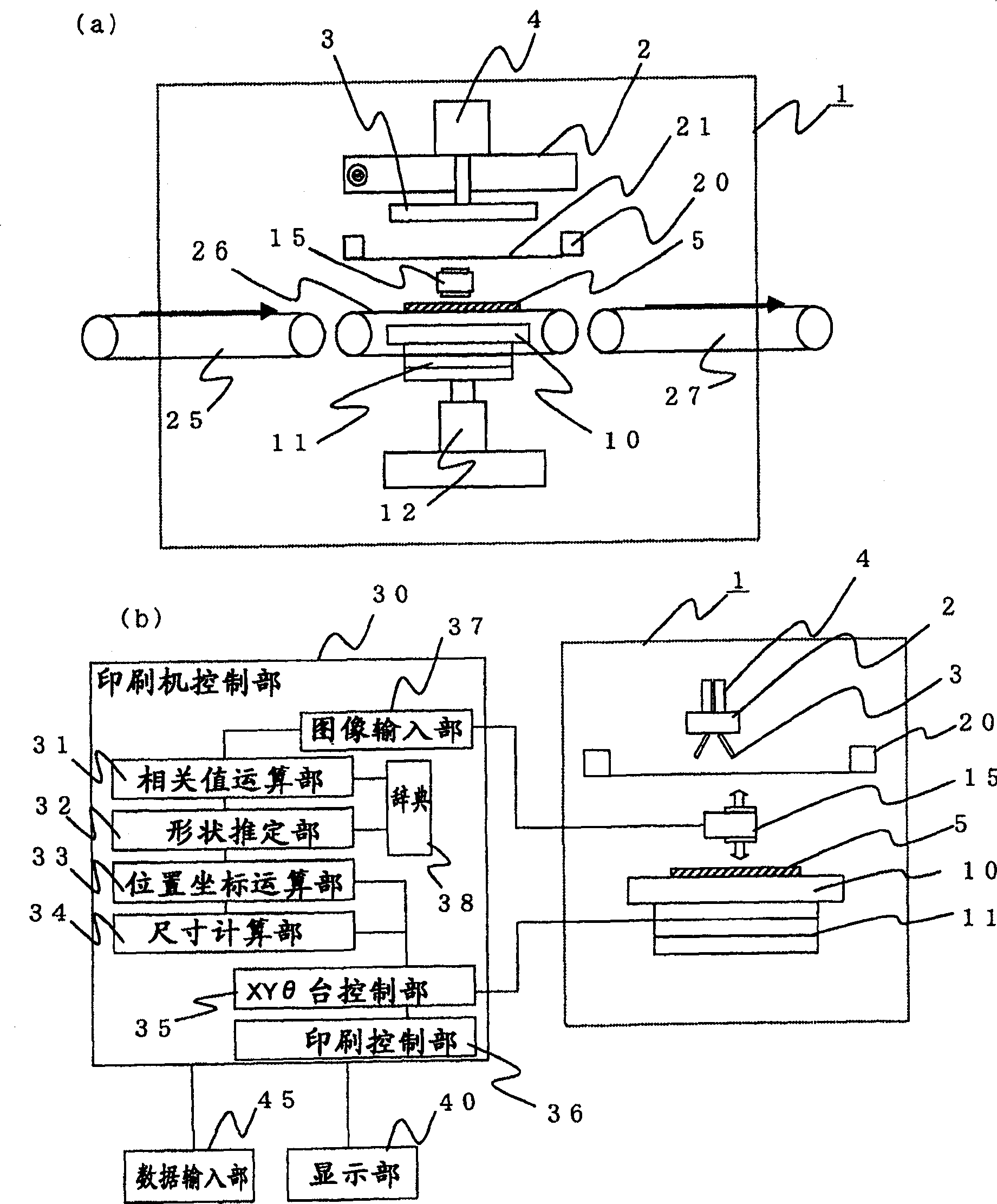
In addition, in order to determine the size of the template, it is necessary to input the size of the mark. In the case of position calculation with an accuracy of ±0.01mm, it is required to input the size to 0.001mm, and it is actually very difficult to input it correctly.

Method used


Image

  • Solder paste printing system
  • Solder paste printing system
  • Solder paste printing system

Examples


Embodiment Construction

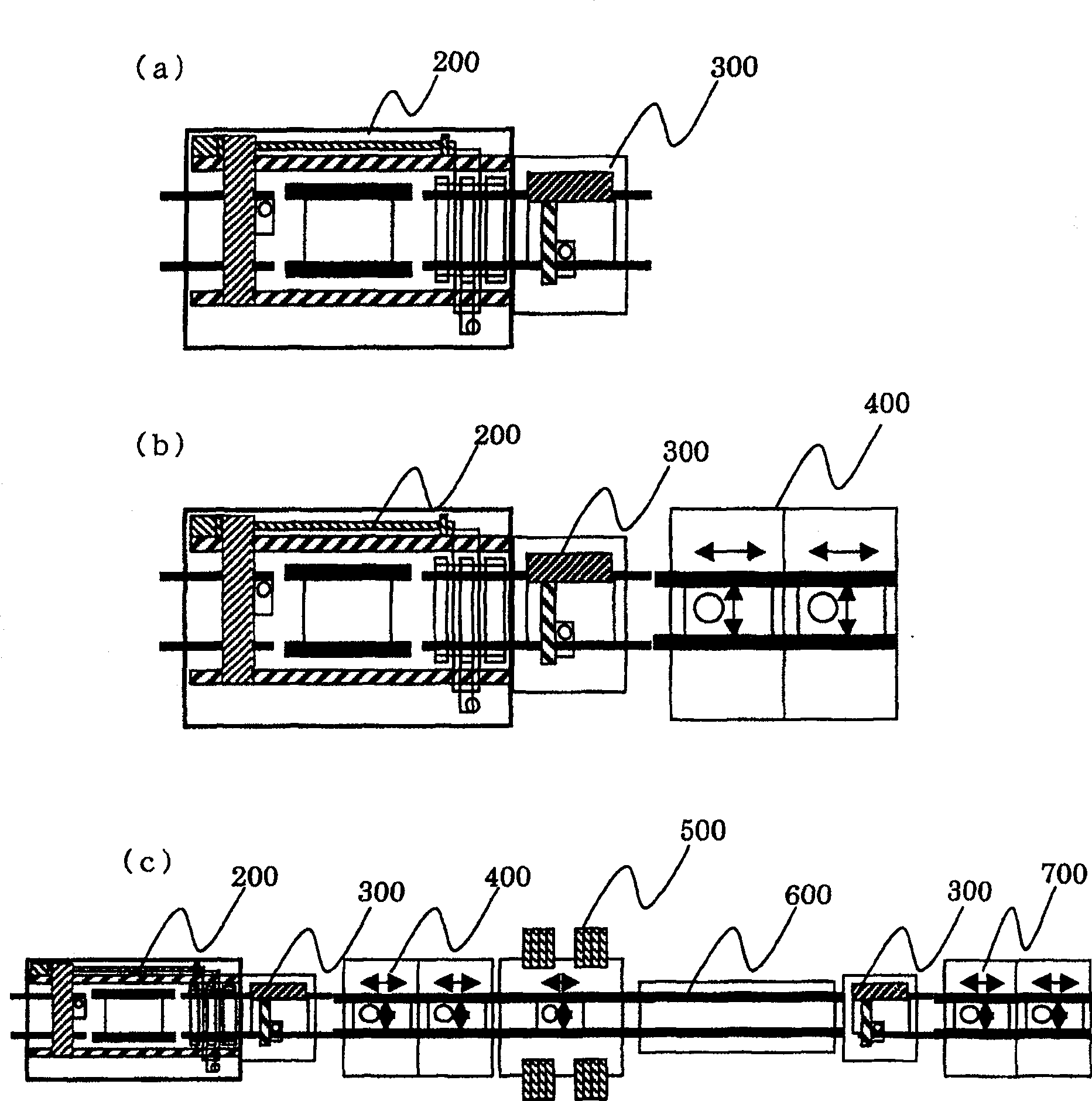
[0039] figure 1 The arrangement of each device of the solder paste printing system of the present invention is shown.

[0040] As a representative example of the printing system of the present invention, in addition to the screen printing unit 200, its configuration also includes an inspection unit 300 for inspecting the results printed on the screen printing unit (hereinafter referred to as printing unit) 200, and depending on the situation, In case the inspection unit 300 detects a poorly printed but repairable printing state, a plurality of dispenser units 400 are used to repair it.

[0041] Conventionally, in the case of applying solder paste, the solder paste to be applied is supplied to the mask surface in the printing unit 200, and after the preparation is completed, after the position of the mark is pointed and recognized, automatic operation is started, and printing After soldering the paste, the substrate is transferred to the downstream device. In this regard, as ...


PUM


Abstract

Provided are a screen printing device and a printing system including the same. In a solder paste printing system equipped with a screen printing device, in order to improve the printing accuracy of the screen printing device, even if printing defects occur in the screen printing machine, it is necessary to be able to correct the defects that may be repaired in the system. Repairs are performed within the system to increase the productivity of the product. For this reason, the squeegee used in the printing of the screen printing apparatus has a structure using a metal squeegee having two-stage elasticity, and at the same time, an inspection unit for inspecting the printing state after the printing is completed, and an inspection unit for As a result, the configuration of the distributor unit for repairing the defective printed circuit board was adopted, and the inspection result was transmitted to the screen printing apparatus and reflected in the printing of the next circuit board.

Description

technical field [0001] The present invention relates to a screen printing device, and more particularly to a printing device for printing solder paste and a printing system using the same. Background technique [0002] As a conventional screen printing machine, there is a device disclosed in JP-A-5-200975. The screen printing machine has: a stage portion with a substrate carrying in conveyor, a substrate carrying out conveyor, and a lifting mechanism; a mask having a transfer pattern as an opening; a squeegee, a squeegee lifting mechanism, and a horizontal direction. Applicator heads for moving mechanisms; controls for controlling these mechanisms. After placing the substrate loaded into the device on the stage, raise the stage part to bring the substrate close to the mask, and fill the opening of the mask with milky solder or the like while touching the mask to the substrate with a squeegee. Then, by lowering the stage part, the substrate and the mask are separated, and t...

Claims


Application Information

Patent Timeline
Patent Type & Authority Patents(China)
IPC IPC(8): B41F33/00B41F15/08B41F15/44H05K3/12
Inventor 栗原弘邦本间真矢作睦行川边伸一郎向井范昭
Owner HITACHI LTD
Learn More