High frequency power amplifier circuit

A power amplifier circuit and high-frequency amplifier technology, applied in power amplifiers, electrical components, transmission systems, etc., can solve problems such as low output power and input signal distortion, and achieve the effect of increasing output power and reducing distortion

Active Publication Date: 2017-12-08
CHINA MARITIME POLICE ACADEMY
View PDF10 Cites 0 Cited by
  • Summary
  • Abstract
  • Description
  • Claims
  • Application Information

AI Technical Summary

Problems solved by technology

However, single-tube amplifiers are usually used, and the output power is low. In order to overcome this technical problem, the prior art provides a cascode amplifier. They share a bias circuit, which will cause distortion of the input signal

Method used


Image

  • High frequency power amplifier circuit
  • High frequency power amplifier circuit
  • High frequency power amplifier circuit

Examples


no. 1 example

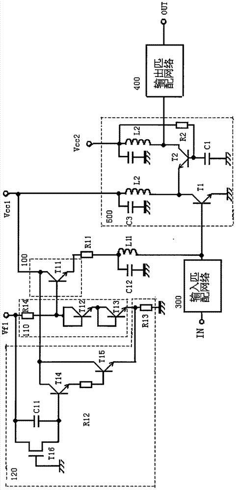
[0019] figure 1 It is the circuit diagram of the high-frequency power amplifier provided by the first embodiment of the present invention, such as figure 1 As shown, the high-frequency power amplifier provided by the first embodiment of the present invention includes a high-frequency signal input terminal IN, an input matching network 300, a high-frequency amplifier 500, an output matching network 400, a high-frequency signal output terminal OUT, and a first bias circuit 100 and a second bias circuit, wherein the high frequency amplifier 500 includes: a first transistor T1, a second transistor T2, a first high frequency choke coil L1, a second high frequency choke coil L2 and a capacitor C1, the first A bias circuit 100 is connected to the base of the first transistor T1 for providing a bias current to the base of the first transistor T1 according to the control voltage Vcon1; the emitter of the first transistor T1 is grounded, and the collector is connected to the first high ...

no. 2 example

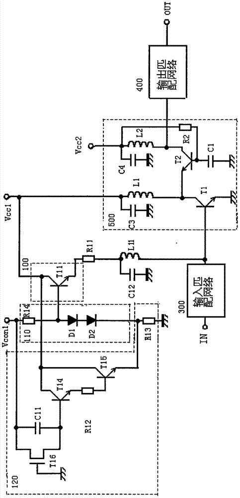
[0025] Combine below figure 2 Describe the high-frequency power amplifier circuit provided by the second embodiment of the present invention, such as figure 2 As shown, the difference between the high-frequency power amplifying circuit provided by the second embodiment of the present invention and the high-frequency power amplifying circuit provided by the first embodiment is only that the first power supply circuit used to provide the reference voltage for the first bias circuit The configurations are different. In the second embodiment, the first power supply circuit 110 includes a resistor R14, a diode D1 and a diode D2. The first end of the resistor R14 is connected to the control voltage Vcon1, the second end is connected to the anode of the diode D1, and the cathode of the diode D1 is connected to the ground through the surge circuit. The control signal Vcon1 is used to control the start and stop of the bias circuit 100. In the first power supply circuit 110, the res...

no. 3 example

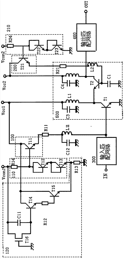
[0027] Combine below image 3 Describe the high-frequency power amplifying circuit provided by the third embodiment of the present invention, such as image 3 As shown, the high-frequency power amplifying circuit provided by the third embodiment of the present invention is different from the high-frequency power amplifying circuit provided by the first embodiment only in that the second bias circuit is different. In the second embodiment, the transistor T2 The bias circuit for providing the bias voltage includes a transistor T21, the collector of the transistor T21 is connected to the second power supply Vcc2, and the emitter is connected to the base of the transistor T2 through the resistor R21 and the high frequency choke coil L21 in turn. The second reference voltage is provided by the second power supply circuit 210, which is used to control the bias of the transistor T2. The second power supply circuit 210 includes a resistor R24, a transistor T22, and a transistor T23. The...


PUM


Abstract

The invention relates to a high frequency power amplifier circuit. The high frequency power amplifier circuit comprises a high frequency amplifier and is characterized in that the high frequency amplifier comprises a first transistor, a second transistor, a first high frequency choke, a second high frequency choke, a first bias circuit, a second bias circuit, and a capacitor, the first bias circuit is connected with a base electrode of the first transistor and is used for providing bias circuit for the base electrode of the first transistor according to a control voltage, an emitting electrode of the first transistor is grounded, a collecting electrode is connected with a first power through the first high frequency choke, the collecting electrode of the first transistor is further connected with an emitting electrode of the second transistor, a base electrode of the second transistor is grounded through the capacitor, a collecting electrode is connected with a second power through the second high frequency choke, and the second bias circuit is connected with the base electrode of the second transistor and is used for providing bias circuit for the base electrode of the second transistor. The high frequency power amplifier circuit provided in the invention lowers distortion, and increases output power.

Description

technical field [0001] The invention relates to a high-frequency power amplifier circuit, in particular to a high-frequency power amplifier used in mobile phones. Background technique [0002] Generally, in an amplitude modulation signal, especially in multi-value modulation such as QAM (Quadrature Amplitude Modulation), a high-frequency power amplifier needs to be configured in a transmission circuit for transmitting power to an antenna, in order to keep the signal from being distorted , the high-frequency power amplifier needs to linearly amplify the input high-frequency modulation signal linearly. Therefore, a high-frequency power amplifier used as the final stage of a mobile phone usually works in a class A or class A and B state. However, single-tube amplifiers are usually used, and the output power is low. To overcome this technical problem, the prior art provides a cascode amplifier, which share a bias circuit, which will cause distortion of the input signal. Conte...

Claims


Application Information

Patent Timeline
Patent Type & Authority Applications(China)
IPC IPC(8): H03F3/20H04B1/40
CPCH03F3/20H04B1/40
Inventor 应忠于连增水
Owner CHINA MARITIME POLICE ACADEMY
Why Eureka
Try Eureka