
Crankcase structure for needling machine

A crankcase, acupuncture machine technology, used in acupuncture machines, mechanical equipment, textiles and papermaking, etc., can solve problems such as machine vibration, substantial complexity, and lateral oscillation

Inactive Publication Date: 2009-10-07
常熟市伟成非织造成套设备有限公司
View PDF6 Cites 2 Cited by
  • Summary
  • Abstract
  • Description
  • Claims
  • Application Information

AI Technical Summary

Problems solved by technology

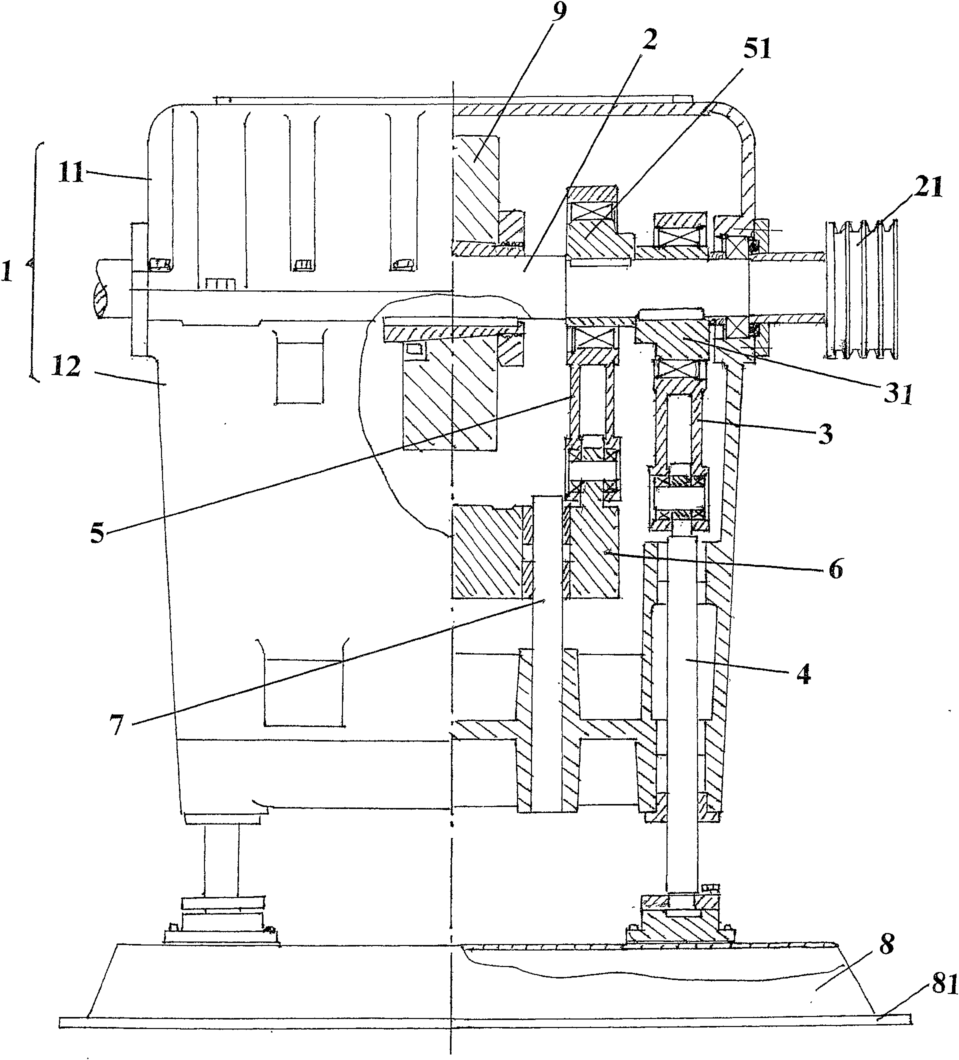
However, it is difficult or even impossible for this structure to offset the inertial force produced by the complicated motion of the first and second connecting rods 3 and 5, because as known in the industry, the movement of the connecting rods seems to be simple, but in fact it is extremely complicated. As far as this structure is concerned In other words, the big head of the connecting rod (the first and second connecting rods 3, 5, the same below) exhibits circular motion, while the middle part of the connecting rod has both circular motion and up and down motion, and furthermore, the small end of the connecting rod presents a complete Therefore, although the inertial force of the connecting rod is inconspicuous, it is proportional to the square of the speed, so when the speed of the acupuncture machine is greater than 1000n / min, it will seriously cause machine vibration and lateral movement. swing, which is present by the figure 1 The main reason why the crankcase structure of the disclosed single-shaft, single-connecting rod, single push rod, single-needle beam, and single-needle plate needle loom cannot increase the needling speed and affect production capacity

Method used


Image

  • Crankcase structure for needling machine
  • Crankcase structure for needling machine
  • Crankcase structure for needling machine

Examples


Embodiment Construction

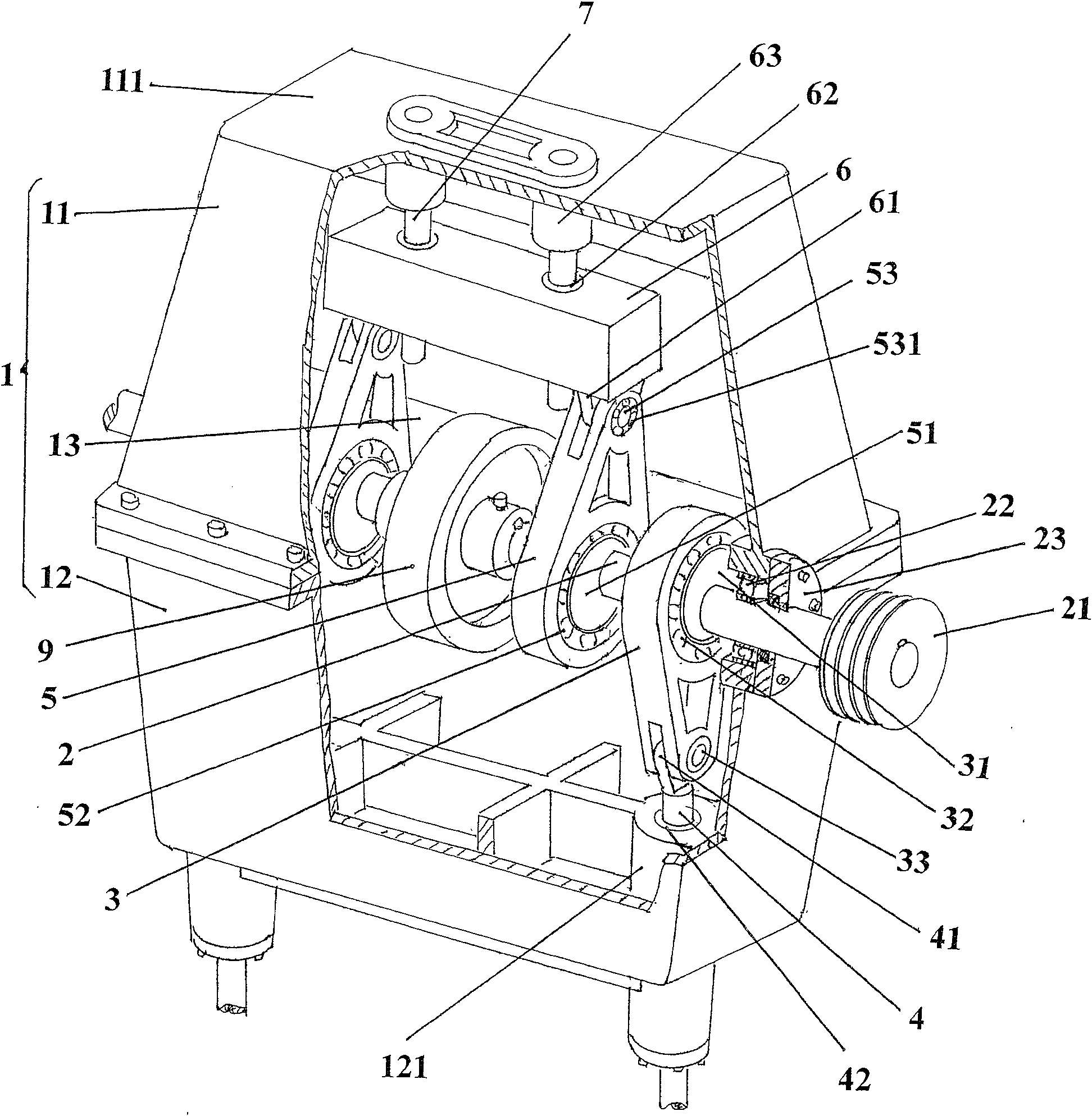
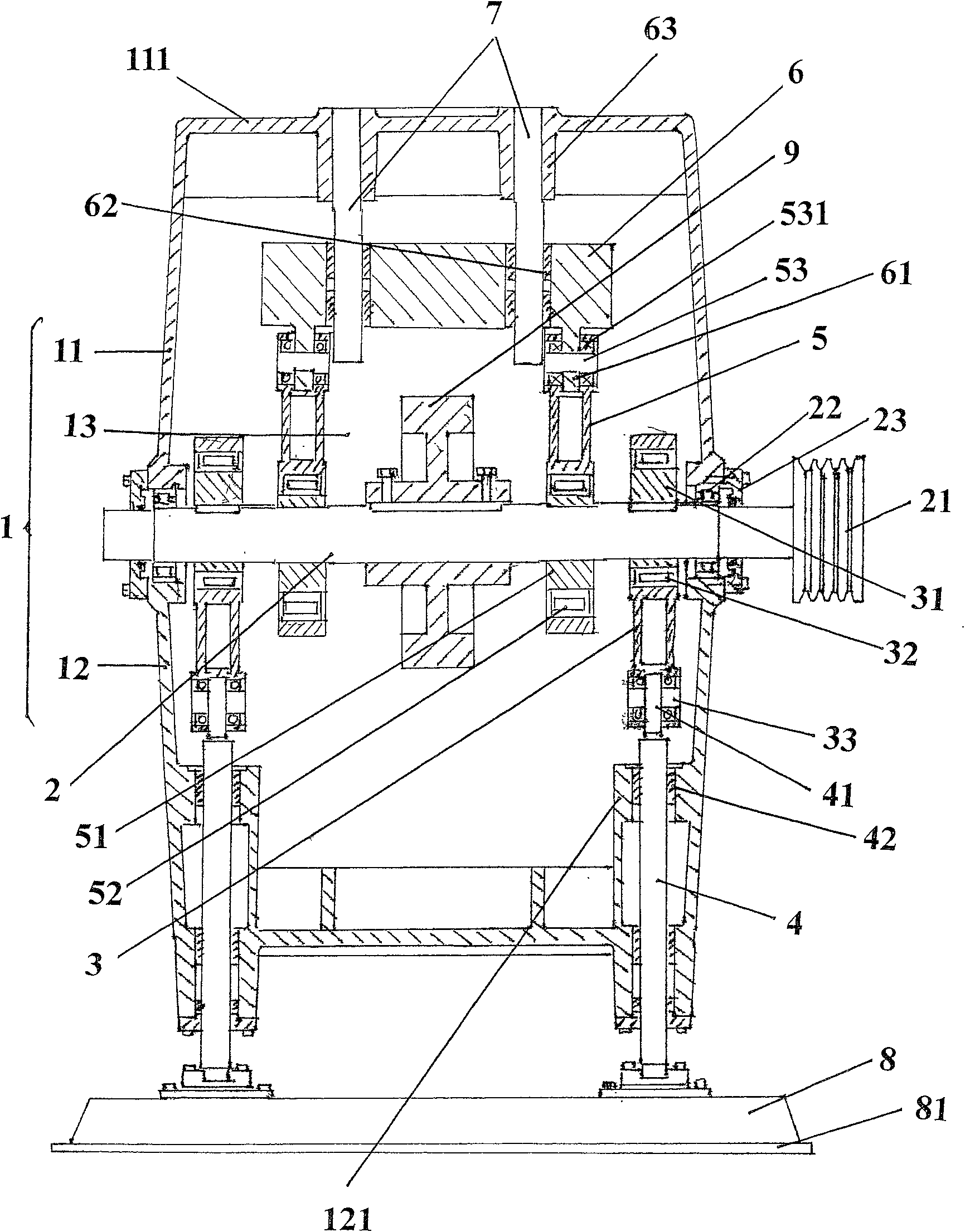
[0016] see figure 2 with image 3 , the given box 1 is composed of upper and lower shells 11, 12 cooperating with each other, and the cavities of the upper and lower shells 11, 12 jointly constitute the box cavity 13 of the box 1. Depend on figure 2 Clearly, since the shapes of the upper and lower casings 11, 12 are substantially the same, they can be said to be symmetrical structures. A main shaft 2 is located in the middle of the height direction of the box body 1, more precisely, it is located at the mutual joint position of the upper and lower housings 11, 12, specifically: the two ends of the main shaft 2 respectively pass through the first bearing 22 and add The shaft cover 23 realizes pivoting with the box body. Taking the illustrated position as an example, the main shaft 2 is fixed with a transmission wheel 21 at the left end extending out of the box body 1 , while the right end of the main shaft 2 also extends out of the box body 1 . The reason why the right en...


PUM


Abstract

The crankcase for needle punching machine as one non-woven fabric making machine has the structure including one case, one main shaft with ends on the case, one pair of first link rods, and one pair of second link rods located in the first pair of link rods, one pair of guide rods, one pair of push rods, and one flywheel on the main shaft. It features one balance weight over the main shaft to slip fit the guide rods. The crankcase in the improved structure can raise the needle punching speed of the needle punching machine for high output.

Description

technical field [0001] The invention belongs to the technical field of non-woven machinery, and in particular relates to a crankcase structure of an acupuncture machine. The improvement of the crankcase structure of the engine. Background technique [0002] Due to the relatively simple structure and low cost of single-shaft-driven single-link, single-push-rod, single-needle beam, and single-needle plate needlelooms, it is widely used in non-woven product manufacturers, but this needle The machine also has its own disadvantages, that is, the speed is usually only around 600-800n / min, so the production efficiency is relatively low. [0003] In view of the above, the Chinese Invention Patent Application Publication No. CN1916258A discloses a transmission balance mechanism of an acupuncture machine. It is developed based on the crankcase structure and has a strong pertinence. Since the scheme can make the modified crankcase meet the needling speed of 1200-1500n / min required b...

Claims


Application Information

Patent Timeline
Patent Type & Authority Patents(China)
IPC IPC(8): D04H18/00F16H33/08F16H21/18D04H18/02
Inventor 王卫成赵军
Owner 常熟市伟成非织造成套设备有限公司
Learn More