Ground speed testing methods suitable for optical fibre gyroscope strap-down inertial navigation system

A strapdown inertial navigation and fiber optic gyroscope technology, which is applied to Sagnac effect gyroscopes and navigation through speed/acceleration measurement, can solve problems such as the influence of the system's ground speed detection accuracy, reduce the amount of calculation, and improve the ground speed. High-speed output accuracy and the effect of saving limited resources

Inactive Publication Date: 2009-10-07
HARBIN ENG UNIV
View PDF3 Cites 3 Cited by
  • Summary
  • Abstract
  • Description
  • Claims
  • Application Information

AI Technical Summary

Problems solved by technology

[0004] In order to solve the problem that the rowing effect affects the system ground speed detection accuracy in a high dynamic environment or a high frequency vibration environment, the present invention provides a ground speed detection method suitable for the fiber optic gyro strapdown inertial navigation system

Method used


Image

  • Ground speed testing methods suitable for optical fibre gyroscope strap-down inertial navigation system
  • Ground speed testing methods suitable for optical fibre gyroscope strap-down inertial navigation system
  • Ground speed testing methods suitable for optical fibre gyroscope strap-down inertial navigation system

Examples


Embodiment Construction

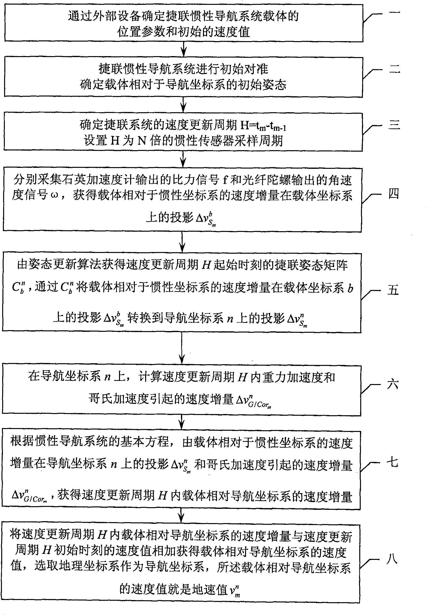
[0029] The ground speed detection method suitable for the fiber optic gyro strapdown inertial navigation system described in this embodiment, the specific steps are as follows:

[0030] Step 1, determining the position parameters of the carrier and the initial ground speed value through external equipment;

[0031] Step 2, the strapdown inertial navigation system performs initial alignment, and determines the initial attitude of the carrier relative to the navigation coordinate system n;

[0032] Step 3. Determine the ground speed update period H=t m -t m-1 , the ground speed update period H is equal to the rowing compensation period; H is set to N times the inertial sensor sampling period, and the N is an integer greater than 0;

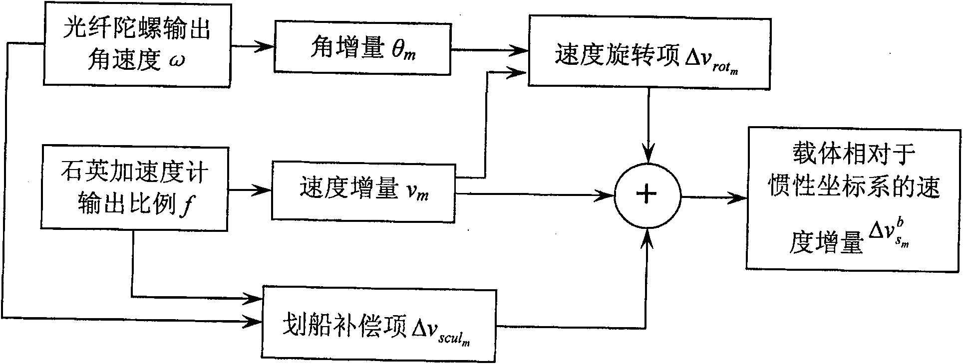
[0033] Step 4: collect the specific force signal f output by the quartz accelerometer and the angular velocity signal ω output by the fiber optic gyroscope, and calculate the projection of the velocity increment of the carrier relative to the iner...


PUM


Abstract

The invention relates to a ground speed detection method suitable for a fiber optic gyro strapdown inertial navigation system, and relates to a rowing compensation method. It solves the problem that the rowing effect affects the accuracy of ground speed detection in a high dynamic environment or a high frequency vibration environment. The present invention obtains the velocity measurement increment and the angle increment measurement value of the carrier relative to the inertial coordinate system by the specific force signal and the angular velocity signal respectively in the ground speed update period, and then obtains the velocity rotation item; at the same time, the specific force signal and the angular velocity signal The cross-product item of is fitted to obtain the rowing compensation item; the velocity increment of the carrier relative to the inertial coordinate system in the update cycle is calculated by the speed rotation item and the rowing compensation item, and then the obtained velocity increment is projected into the navigation coordinate system n, Calculate the speed increment caused by the acceleration of gravity and Coriolis acceleration in the navigation coordinate system n, and finally calculate the ground speed value through the basic equation of the inertial navigation system. The present invention is suitable for the situation that the carrier is in high frequency vibration or high maneuverability.

Description

technical field [0001] The invention relates to a ground speed detection method of an optical fiber gyro strapdown inertial navigation system. Background technique [0002] In a strapdown inertial navigation system, two key calculations are included. One is to update the calculation of the attitude of the carrier, and the other is to update the calculation of the ground speed of the carrier (the speed value of the navigation coordinate system n relative to the earth coordinate system). In the attitude update calculation, if there is a situation where the carrier angular velocity vector rotates, a coning error will be introduced. In the calculation of updating the ground speed of the carrier, the situation is more complicated, because to obtain the ground speed information of the carrier, it is necessary to integrate the force signal in the navigation reference coordinate system. This integration process is usually divided into two steps: first, The specific force signal se...

Claims


Application Information

Patent Timeline
Patent Type & Authority Patents(China)
IPC IPC(8): G01C21/16G01C21/18G01C19/72
Inventor 孙枫奔粤阳高伟周广涛陈世同于强高洪涛
Owner HARBIN ENG UNIV
Why Eureka
Try Eureka