Heated wall surface cooling structure and gas turbine impeller vane with the same

A technology for gas turbine blades and cooling structures, applied in the directions of blade support elements, mechanical equipment, engine elements, etc., can solve the problems of easy fatigue failure of materials, limited cooling capacity, uneven cooling, etc., so as to avoid continuous increase and decrease of thermal stress. Wall temperature gradient, the effect of providing cooling efficiency

Active Publication Date: 2009-10-21
TSINGHUA UNIV
View PDF4 Cites 1 Cited by
  • Summary
  • Abstract
  • Description
  • Claims
  • Application Information

AI Technical Summary

Problems solved by technology

In short, the existing film cooling of gas turbines has the following deficiencies: limited cooling capacity; the use of discrete through holes leads to uneven cooling, correspondingly large thermal stress, and the material is prone to fatigue failure
Sweat cooling has the following disadvantages: the porous medium forming sweat cooling has poor strength; it is easy to cause overall failure due to local blockage

Method used


Image

  • Heated wall surface cooling structure and gas turbine impeller vane with the same
  • Heated wall surface cooling structure and gas turbine impeller vane with the same
  • Heated wall surface cooling structure and gas turbine impeller vane with the same

Examples


Embodiment Construction

[0031] The principle and specific structure of the present invention will be further described below.

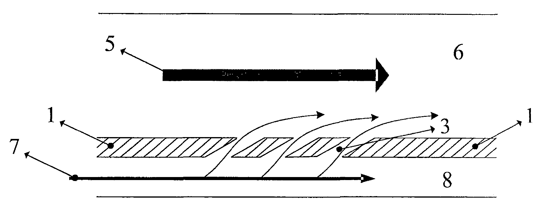
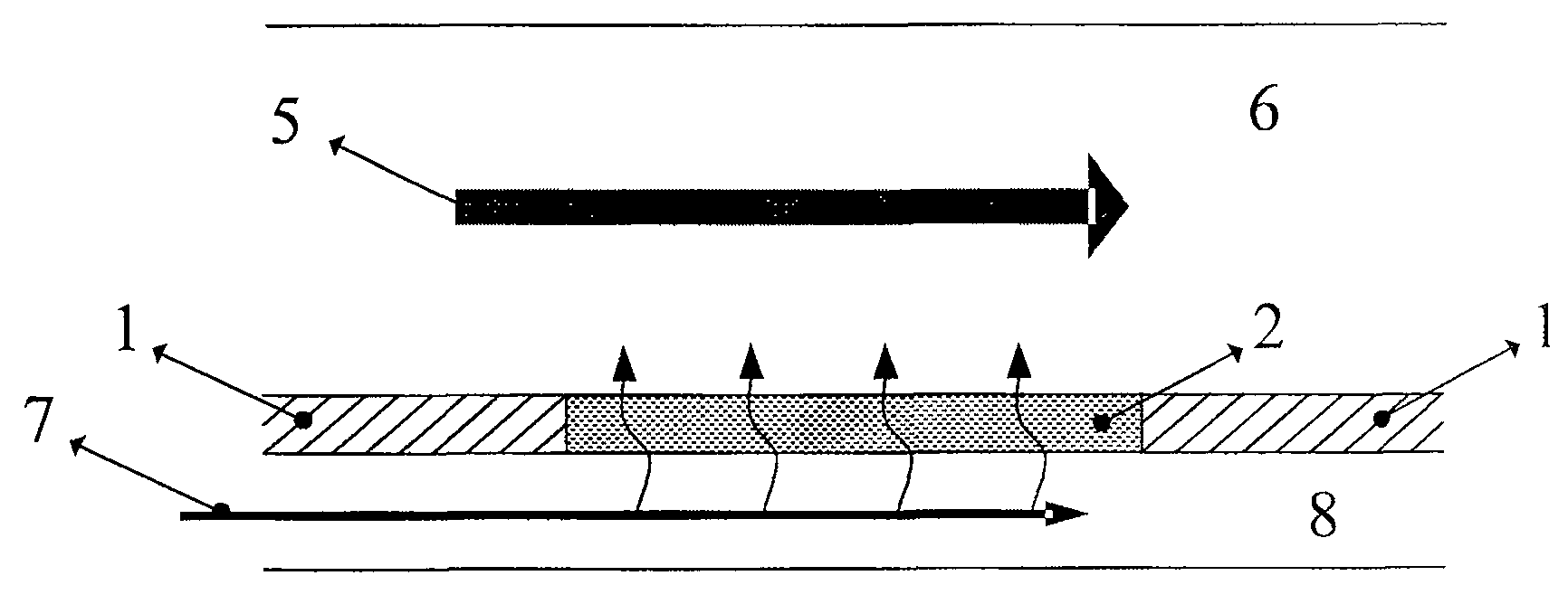
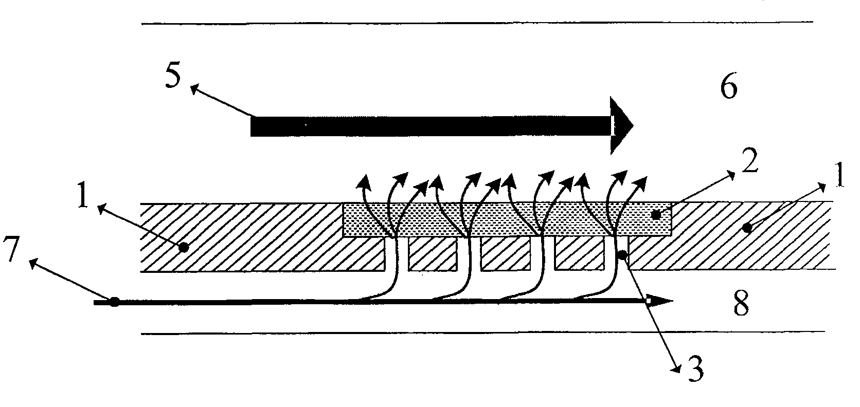
[0032] The heated wall surface cooling structure provided by the present invention has a dense wall surface layer 1, and the dense wall surface layer 1 is provided with a plurality of discrete through holes 3 for coolant to pass through, and the heated side of the dense wall surface layer 1 is covered with a porous medium layer 2, Thereby the porous medium layer 2 and the dense wall surface layer 1 having a plurality of discrete through-holes 3 form a double-layer stacked structure, and the described porous medium layer 2 covers the outlets of all the discrete through-holes 3; the described porous medium layer 2 is A whole piece of continuous distribution is continuously and completely covered on the heated side of the dense wall surface layer 1, so that the outlets of all the discrete through holes 3 are covered by the whole piece of porous medium layer 2; or the porous medi...


PUM


Abstract

A heated wall surface cooling structure and a gas turbine blade using the cooling structure, the cooling structure has a dense wall surface layer, the dense wall surface layer is opened with a plurality of discrete through holes for coolant to pass through; the heated side of the dense wall surface layer is covered with a porous medium layer , making the porous medium layer and the dense wall surface layer with a plurality of discrete through-holes form a double-layer stacked structure, and the outlets of the discrete through-holes communicate with the porous medium layer. The porous medium layer can cover the dense wall surface layer continuously, or only cover the partial area of ​​the outlet of the discrete through-hole. The invention combines the characteristics of air film cooling and sweat cooling, fully combines the advantages of the two cooling methods, can effectively improve the cooling efficiency on the wall surface, reduce the temperature gradient of the wall surface, and avoid the continuous increase of material thermal stress. At the same time, the strength of the cooling structure of the present invention is sufficient for common impeller machines.

Description

technical field [0001] The invention relates to a cooling structure for a heated wall surface and a gas turbine blade using the cooling structure, belonging to the technical field of thermal engineering. Background technique [0002] Necessary cooling of mechanical structures in high-temperature environments to ensure safe operation of structures has always been a common problem in production and life. In applications involving heat engines, high-temperature surfaces that need to be cooled abound, such as cylinder walls of diesel and gasoline engines for vehicles, thrust chambers of rockets, blades of gas turbines, outer walls of ultra-high-speed aircraft, inner cylinders of super-combustion engines, etc. For gas turbines, increasing thermal efficiency and power means increasing turbine inlet temperature. The turbine inlet temperature, which has been increasing year by year, has exceeded 2000°C, while the maximum heat-resistant temperature of metal parts such as blades is g...

Claims


Application Information

Patent Timeline
Patent Type & Authority Patents(China)
IPC IPC(8): F01D5/18
Inventor 姜培学刘元清王扬平
Owner TSINGHUA UNIV
Why Eureka
Try Eureka