Cross flow fan and air conditioner with the fan

A cross-flow fan, pseudo-random sequence technology, used in air conditioning systems, lighting and heating equipment, components of pumping devices for elastic fluids, etc., can solve the deterioration of air supply noise, increased motor load, blade pitch sound Problems such as the increase in ingredients

Active Publication Date: 2009-10-21
TOSHIBA CARRIER CORP
View PDF8 Cites 4 Cited by
  • Summary
  • Abstract
  • Description
  • Claims
  • Application Information

AI Technical Summary

Problems solved by technology

[0007] In response to these requirements, in the structure of the cross-flow fan described in Patent Document 1, when the outer diameter of the fan is enlarged and the gap between the fan and the heat exchanger installed around the fan is narrowed, the blade pitch noise will be caused. The composition increases, which worsens the air supply noise, and also increases the load on the motor.

Method used


Image

  • Cross flow fan and air conditioner with the fan
  • Cross flow fan and air conditioner with the fan
  • Cross flow fan and air conditioner with the fan

Examples


Embodiment Construction

[0027] Hereinafter, embodiments of a cross-flow fan according to the present invention will be described with reference to the drawings.

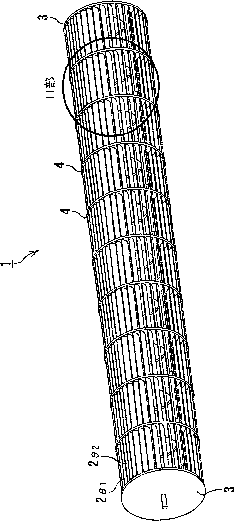
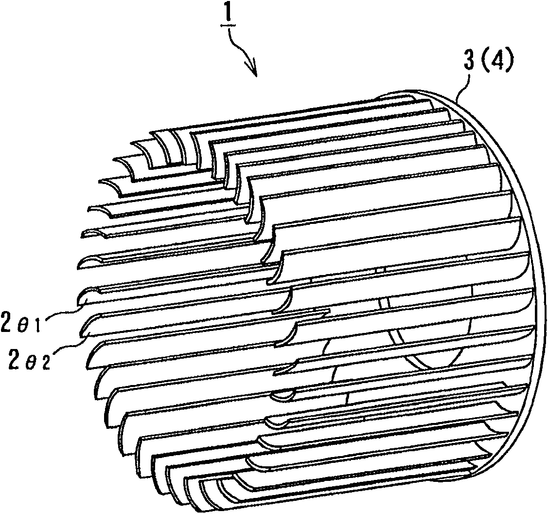
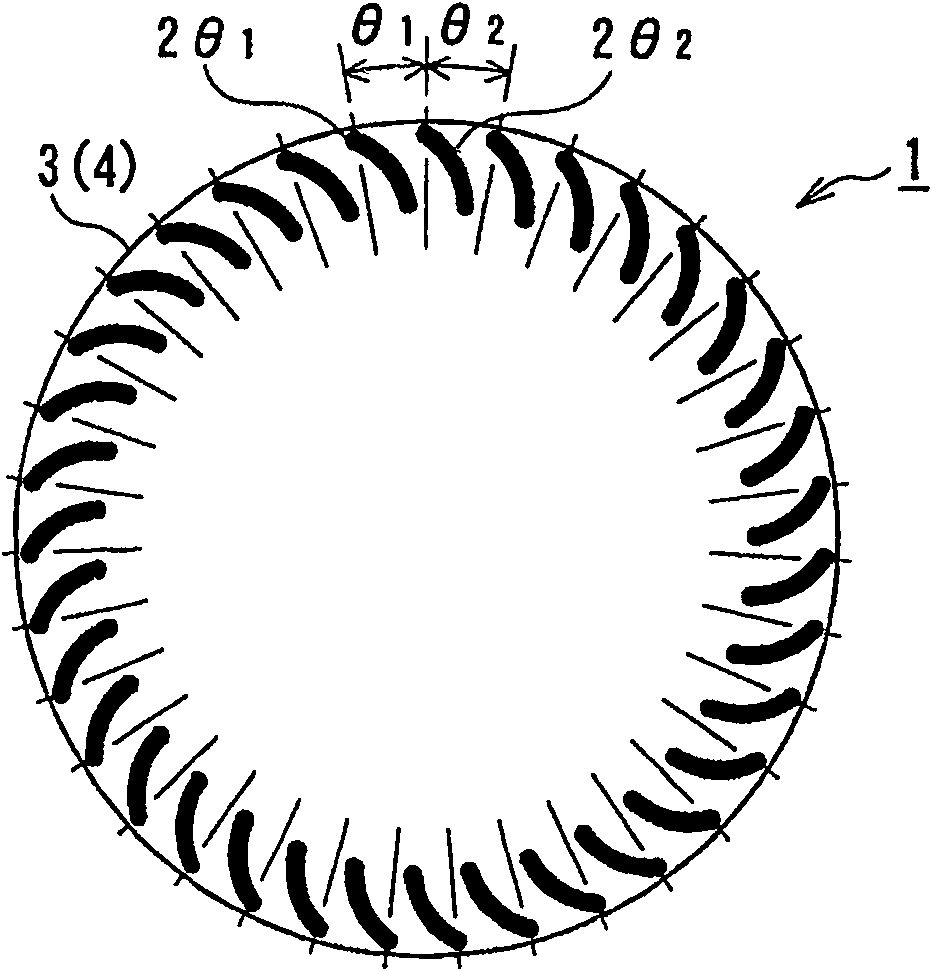
[0028] Such as Figure 1 ~ Figure 3 As shown, the cross-flow fan 1 according to the present invention is provided with: a plurality of arc-shaped blades 2 that are bent forward (outward in the circumferential direction) and have the same shape. θ1 ,2 θ2 , and with the blade 2 installed θ1 ,2 θ2 An end plate 3 or a bulkhead 4, a plurality of vanes 2 θ1 ,2 θ2 (In the way shown in the illustration, it refers to two adjacent blades) with 2 different pitch angles θ 1 , θ 2 Formed periodically, and configured into a ring to form a periodic pseudo-random sequence.

[0029] Further, the blade 2 θ1 ,2 θ2 is configured under the conditions described below. For example, the difference between the above two pitch angles (θ 2 -θ 1 ) offset size Δ is taken as Δ=(θ 2 -θ 1 ) / θ (wherein, θ in the denominator is the pitch angle when the blades ...


PUM


Abstract

A cross flow fan (1) for an air conditioner capable of reducing a load on a motor while reducing the noise of a blower, comprising a plurality of blades (2theta1, 2theta2) and support plates (3, 4) pivotally supporting the plurality of blades (2theta1, 2theta2) at both ends thereof, characterized in that the plurality of blades (2theta1, 2theta2) are disposed annularly on the support plates so as to form a cyclic pseudo-random series while maintaining a periodicity at two different pitch angles (theta1, theta2) so that, when a displacement Delta as the ratio of a difference (theta1 - theta2) between the two pitch angles to a pitch angle (theta) when all blades are disposed at equal intervals is Delta = (theta1 - theta2)/theta, the displacement Delta is 0.09 <= Delta <= 0.26.

Description

technical field [0001] The invention relates to a cross-flow fan used in an air conditioner, in particular to a cross-flow fan capable of increasing the air volume, reducing the noise of the blower and the load of the motor, and an air conditioner provided with the fan. Background technique [0002] Generally, in a cross-flow fan used in an indoor unit of an air conditioner, a tongue is provided on a casing provided around the cross-flow fan in order to prevent backflow of air and improve air blowing efficiency. [0003] However, since the tongue is provided, a vortex is easily additionally generated in the tongue, and when the blade periodically traverses the vortex generated here, the cutting sound of the blade increases. The cutting sound of the blade can be reduced by separating the tongue from the blade, but if the tongue is separated from the blade, the back flow will increase, and there is a problem that the blowing efficiency of the cross flow fan will be reduced. ...

Claims


Application Information

Patent Timeline
Patent Type & Authority Patents(China)
IPC IPC(8): F04D17/04F24F1/00F04D29/28F04D29/66F24F1/0007F24F13/24
CPCF24F13/24F24F1/0025F04D29/666F04D29/283F24F1/0007F04D17/04
Inventor 石岛满义本乡裕子
Owner TOSHIBA CARRIER CORP
Why Eureka
Try Eureka