Supercharge Your Innovation With Domain-Expert AI Agents!

Multi-position quasi memory cell operation method

A technology of storage unit and operation method, applied in information storage, static memory, read-only memory, etc., can solve the problems of high leakage, low starting voltage, poor efficiency of injecting or discharging electrons, etc.

Active Publication Date: 2009-10-21
MACRONIX INT CO LTD
View PDF6 Cites 0 Cited by
  • Summary
  • Abstract
  • Description
  • Claims
  • Application Information

AI Technical Summary

Problems solved by technology

[0005] However, due to the poor efficiency of injecting or ejecting electrons by using the FN tunneling effect, the erasing action and programming action in the known multi-level memory cell operation method are relatively slow
In addition, since the above-mentioned operation method is to expel electrons from the charge storage layer for erasing, the initial voltage of each memory cell in the erasing state is relatively low, resulting in more leakage
Furthermore, since the above-mentioned programming operation of controlling the starting voltage by the length of the programming time is not easy to precisely control the quantity of injected electrons, the starting voltage distribution range of each storage state memory cell is very wide, and it is easy to read. misjudgment

Method used


Image

  • Multi-position quasi memory cell operation method
  • Multi-position quasi memory cell operation method
  • Multi-position quasi memory cell operation method

Examples


Embodiment Construction

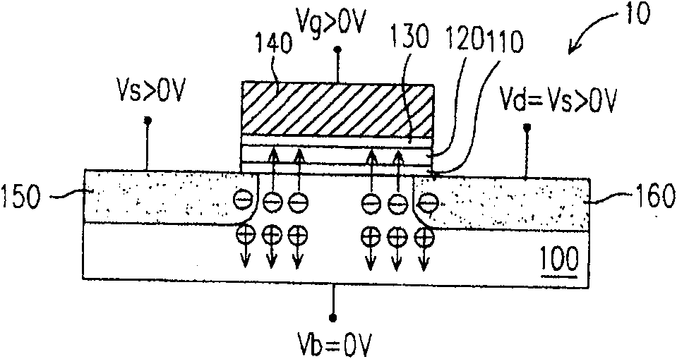
[0021] First of all, it should be noted that although the following embodiments are based on the case where the first conductivity type is P-type, the second conductivity type is N-type, the first-type charges are electrons, and the second-type charges are holes, but with this Those skilled in the art should be able to infer from the description of this embodiment that the multi-level memory cell operation method of the present invention is also applicable to applications where the first conductivity type is N-type, the second conductivity type is P-type, and the first-type charge is empty. hole and the second type of charge is an electron.

[0022] In addition, the charge storage layer in the memory cell to which the operation method of the multi-level memory cell of the present invention is applicable is, for example, a floating gate, a charge-trapping layer or a nano-crystal layer. The material of the floating gate is usually doped polysilicon, the material of the charge tr...


PUM


Abstract

A method for operating a multi-level memory unit, wherein the multi-level memory unit includes a substrate of a first conductivity type, a control gate, a charge storage layer and two source / drain regions of a second conductivity type. The operation method includes an erasing step of injecting first-type charges into the charge storage layer, and a programming step. The programming step includes applying a first voltage to the substrate, a second voltage to the source / drain regions, and a third voltage to the control gate. Wherein, the difference between the first and second voltages is sufficient to generate band-tunneling hot holes in the substrate, and the third voltage can inject the second type charges into the charge storage layer. There are 2n-1 types of the third voltage, wherein n≥2, so as to program the multi-level memory cell to a predetermined storage state among the 2n-1 storage states.

Description

technical field [0001] The present invention relates to a method of operating a semiconductor device, and in particular to a method of operating a multi-level memory cell (Multi-Level Cell, MLC) for a non-volatile memory, which utilizes a double-sided bias (Double -Side Bias, DSB)-Band-To-Band Tunneling Hot Hole (BTBTHH) effect for programming. Background technique [0002] With the rapid growth of information flow, the demand for storage capacity of commonly used electrically erasable programmable non-volatile memory (programmable non-volatile memory) such as flash memory (flash memory) in the market is also increasing. [0003] In order to increase the storage capacity per unit area of ​​non-volatile memory products, the most direct method is to reduce the area of ​​each storage unit, but this method is limited by factors such as the resolution of the lithography process and the electrical properties of the components related to the size. Another method is to make each me...

Claims


Application Information

Patent Timeline
Patent Type & Authority Patents(China)
IPC IPC(8): H01L27/115H01L29/792G11C16/02G11C16/14H10B69/00
Inventor 郭明昌吴昭谊
Owner MACRONIX INT CO LTD
Features
  • R&D
  • Intellectual Property
  • Life Sciences
  • Materials
  • Tech Scout
  • Unparalleled Data Quality
  • Higher Quality Content
  • 60% Fewer Hallucinations
Learn More