Pneumatic thread tensioner and thread handling system

A processing system, tensioner technology, applied in thin material handling, transportation and packaging, textiles and papermaking, etc., can solve the problems of lateral deflection, yarn hydrodynamic damage, high air consumption, etc., to reduce The effect of consumption

Inactive Publication Date: 2009-10-28
IROPA AG (CH)
View PDF6 Cites 0 Cited by
  • Summary
  • Abstract
  • Description
  • Claims
  • Application Information

AI Technical Summary

Problems solved by technology

Continuous operation of the pneumatic yarn tensioner has a high consumption of air, because not only the air flow expands laterally on the circumference of the cylinder, but also the yarn is damaged by the hydrodynamics of the air flow during rest periods
In addition, there is always the danger that the air flow released from the outlet end escapes in front of the cylinder through the middle between the outlet end and the cylinder, so that the yarn may form a loop in said middle where it should not be , the loops can easily become entangled or deflected sideways on the circumference of the cylinder so that when the loom again applies tension to stretch the yarn, the yarn can break

Method used


Image

  • Pneumatic thread tensioner and thread handling system
  • Pneumatic thread tensioner and thread handling system
  • Pneumatic thread tensioner and thread handling system

Examples


Embodiment Construction

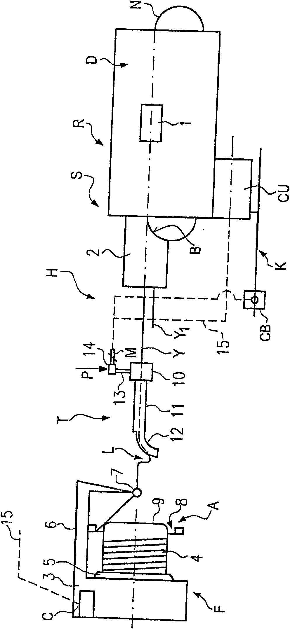
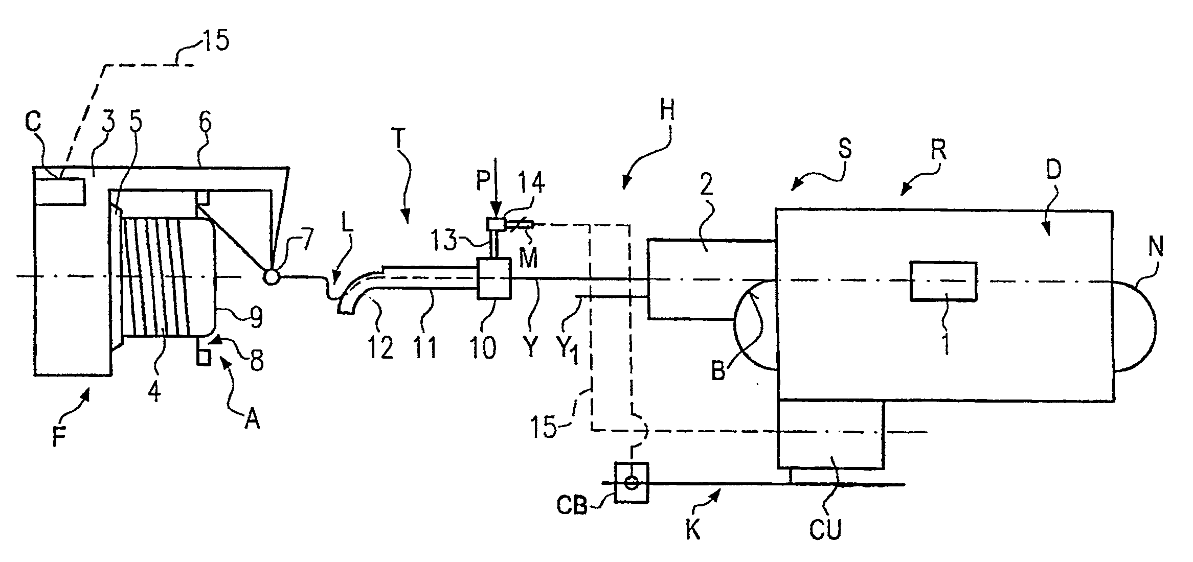
[0024] figure 1 The shown yarn processing system S comprises a weaving machine R, for example a rapier loom or even a braiding machine, and at least one yarn feeding device F and a yarn running path downstream of the yarn feeding device. Pneumatic Yarn Tensioner T.

[0025] A loom R, which is exemplified by a rapier loom, comprises a weaving shed D, a driven yarn guide and yarn take-off grippers B, N for inserting at least one yarn Y, Y1 from at least one yarn channel . The take-off gripper B places the end of the yarn in an insertion and selector device 2 and pulls the yarn to the middle of the knitting shed D, where it takes the yarn in zone 1 The thread end is transferred to the yarn take-off gripper N. The yarn take-off gripper then pulls the yarn entirely through the weaving shed and terminates the insertion process.

[0026]The yarn feeding device F includes a housing 3 and a fixed yarn storage barrel 4, and the yarn Y is wound on the yarn storage barrel in the form ...


PUM


Abstract

The invention relates to a pneumatic yarn tensioner (T) for rapier looms or knitting machines, wherein the airflow deflection surface (19) for deflecting the yarn (Y, Y1) forms the inner wall of the linear channel A seamless extension (12) through which the yarn passes. The invention also relates to a device (H) for varying the flow rate or pressure of the air flow along the deflection plane (19 )flow.

Description

technical field [0001] The invention relates to a pneumatic yarn tensioner and a yarn processing system comprising the pneumatic yarn tensioner. Background technique [0002] In the yarn processing system disclosed in British Patent 1469533A, the pneumatic yarn tensioner is arranged downstream of the yarn feeding device to cooperate with the sliding yarn feeder, and is also arranged upstream of the knitting system of the flat knitting machine, so that the yarn from the tube The direction of the airflow released from the outlet end of the body is opposite to the direction in which the yarn runs. A cylinder is arranged at a considerable distance in front of the air outlet end of the tubular body, the axial direction of the cylinder is positioned transversely to the running direction of the yarn. The extension of the axis of the tube is substantially tangent to the circumference of the cylinder. As the yarn is released from the outlet end, the airflow is deflected on the oute...

Claims


Application Information

Patent Timeline
Patent Type & Authority Patents(China)
IPC IPC(8): D03D47/34D04B15/44B65H59/10D03D47/14D04B15/38
CPCB65H59/105B65H2701/31D04B15/44D03D47/34B65H59/10
Inventor 帕·约瑟夫松
Owner IROPA AG (CH)
Why Eureka
Try Eureka