Rotary quantitative taking out device

A rotary, rotating axis technology, applied in fixed measuring chambers, powder material distribution, etc., can solve problems such as failure to achieve functions, powder leakage from the slide, and obstruction of the slide bucket, so as to achieve smooth movement and reduce production and assembly. Accuracy requirements, the effect of reducing the movement gap

Active Publication Date: 2009-11-18
彭实
View PDF11 Cites 0 Cited by
  • Summary
  • Abstract
  • Description
  • Claims
  • Application Information

AI Technical Summary

Problems solved by technology

[0003] There is a common problem in the existing devices: the sliding bucket is assembled in the fixed space formed by the sliding sleeve to move (including sliding and rotating), or the sliding bucket is fixedly assembled on the rotating shaft to rotate. This kind of fixed structure causes the following disadvantages: 1. If the movement space is too small or the slide is fixed too tightly, it will hinder the movement of the slide and fail to meet the functional requirements; 2. If the movement space is too large or the slide is fixed too loosely, a large Gap, causing the slide to leak powder during movement; 3. If the size of the movement space is uneven or the size of the slide is uneven, the first two situations will occur
[0004] All in all, the current fixed structure has very high requirements on the machining accuracy and assembly accuracy of the sliding bucket and sliding sleeve. Improper precision matching will cause the function to be unrealized
Therefore, in every link of mold, parts production and assembly, a certain dimensional accuracy must be met, and the dimensional accuracy is at the same level as the size of the powder used. According to the current technology and production process, it is impossible to mass-produce manufacture

Method used


Image

  • Rotary quantitative taking out device
  • Rotary quantitative taking out device
  • Rotary quantitative taking out device

Examples


no. 4 Embodiment approach

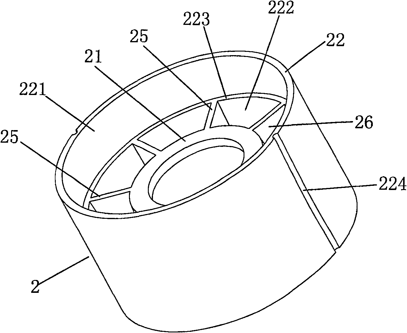
[0062] see Figure 19 and Figure 20 , which is the fourth specific embodiment of the present invention. The main difference between this embodiment and the third embodiment is that: the measuring bucket 2 is provided with a matching cavity 21, and the bottom of the storage tank 1 is put into the matching cavity 21 and connected with the matching cavity. 21 friction fit, and the connection between the measuring bucket 2 and the storage tank 1 is also tightly covered with an elastic sealing ring 3, so as to better play the role of sealing and moisture-proof.

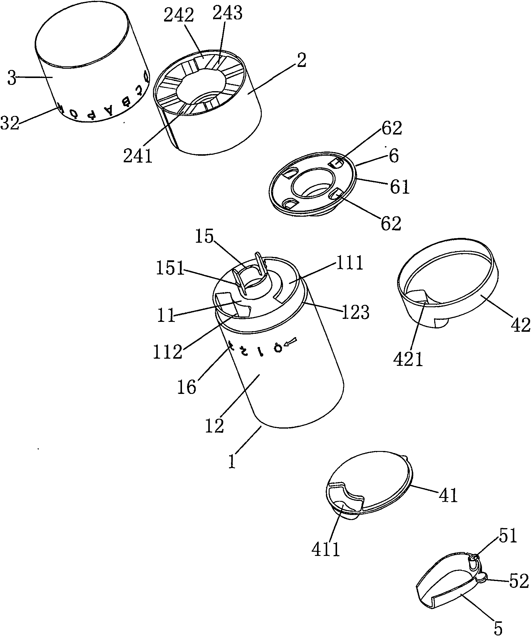
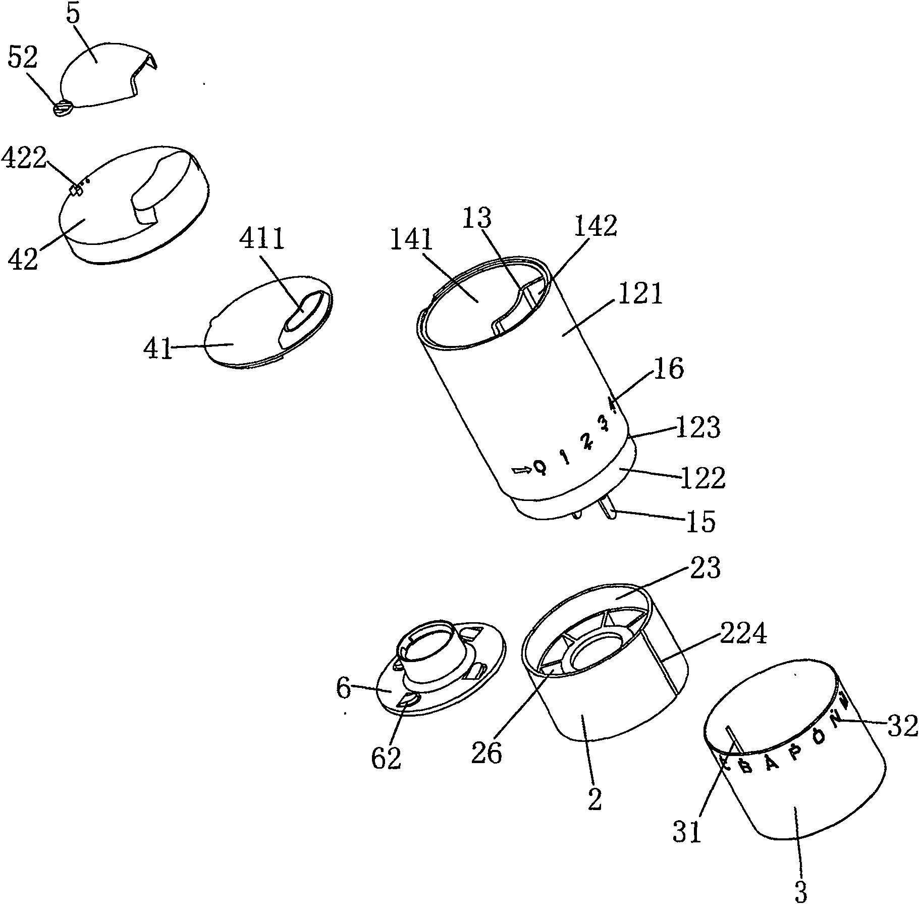
[0063] see Figure 21 to Figure 24 , which is the fifth embodiment of the present invention. The rotary quantitative taking device includes a storage tank 1 , a measuring bucket 2 , a top cover 3 , a bottom cover 4 and an elastic mounting part 5 .

[0064]The storage tank 1 includes a circular bottom plate 11, an annular side plate 12 and a partition 13, the side plate 12 extends vertically upward from the edge of the ...


PUM


Abstract

The invention discloses a rotary quantitative taking device, which comprises a storage tank, a measuring bucket and an elastic mounting part. The storage tank has a tank cavity and a mating surface at the bottom thereof, and the tank cavity is divided into phases and partitioned by a partition plate. The powder inlet chamber and the powder outlet chamber, the measuring bucket is pressed against the fitting surface by the elastic force of the mounting part and can rotate around the axis of rotation against the fitting surface, the measuring bucket has at least one Circle quantitative groove, each circle quantitative groove includes at least two mutually isolated quantitative grooves, the measuring bucket has at least two working positions on its rotation track, and at least one quantitative groove communicates with the powder inlet chamber in each working position. At least another quantitative groove communicates with the powder outlet chamber. Through the elastic mounting parts, the measuring bucket is always pressed against the mating surface of the storage tank with proper elastic force, which can effectively reduce the movement gap between the measuring bucket and the storage tank and make the measuring bucket move smooth.

Description

technical field [0001] The invention relates to a quantitative taking device for taking fluid substances such as powder or granules. Background technique [0002] The existing powder taking devices are composed of a sliding sleeve and a sliding bucket. The sliding bucket is installed on the sliding sleeve and can slide or rotate relative to the sliding sleeve. pink. [0003] There is a common problem in the existing devices: the sliding bucket is assembled in the fixed space formed by the sliding sleeve to move (including sliding and rotating), or the sliding bucket is fixedly assembled on the rotating shaft to rotate. This kind of fixed structure causes the following disadvantages: 1. If the movement space is too small or the slide is fixed too tightly, it will hinder the movement of the slide and fail to meet the functional requirements; 2. If the movement space is too large or the slide is fixed too loosely, a large 3. If the size of the movement space is uneven or the ...

Claims


Application Information

Patent Timeline
Patent Type & Authority Patents(China)
IPC IPC(8): B65D83/06G01F11/28
Inventor 彭实
Owner 彭实
Why Eureka
Try Eureka