Sputtering device and method

A sputtering and sputtering chamber technology, applied in the field of sputtering, can solve the problems of inability to form thickness, low production efficiency, uniform coating, etc., and achieve the effect of simple and convenient operation and improved production efficiency

Inactive Publication Date: 2009-11-18
HONG FU JIN PRECISION IND (SHENZHEN) CO LTD +1
View PDF6 Cites 2 Cited by
  • Summary
  • Abstract
  • Description
  • Claims
  • Application Information

AI Technical Summary

Problems solved by technology

[0004] However, most of the existing sputtering devices are designed for regular planar substrates and can only form coatings on the surface of the substrate opposite to the target. Therefore, it is necessary to replace the substrate several times when coating irregular shaped workpieces such as lens mounts. location, so that the production efficiency is low, and sometimes it is impossible to achieve complete plating, and it is also impossible to form a uniform thickness of the coating

Method used


Image

  • Sputtering device and method
  • Sputtering device and method
  • Sputtering device and method

Examples


Embodiment Construction

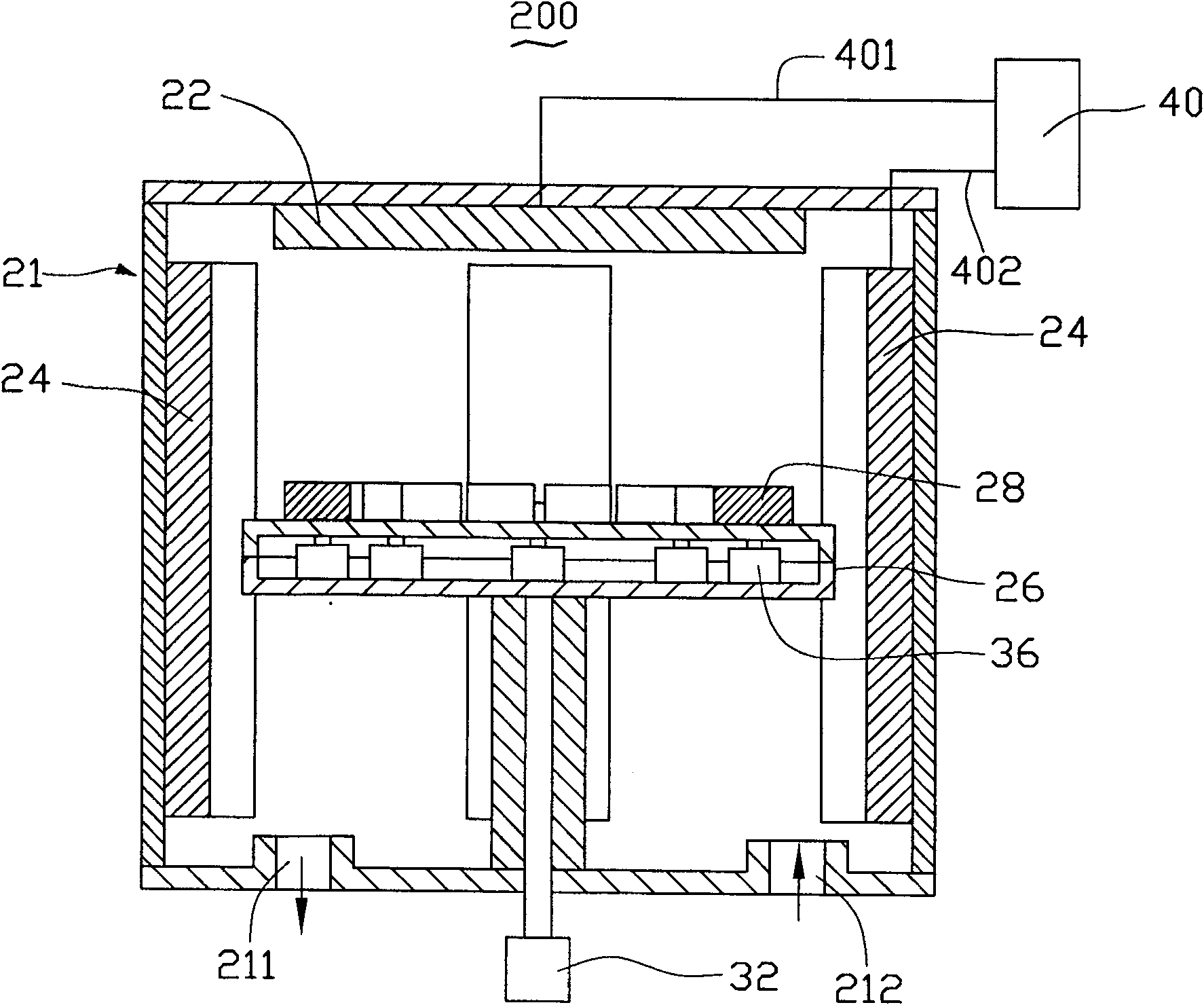
[0014] A sputtering device for sputtering workpieces with irregular shapes and a sputtering method using the sputtering device will be described below by taking sputtering on the surfaces of multiple workpieces as an example.

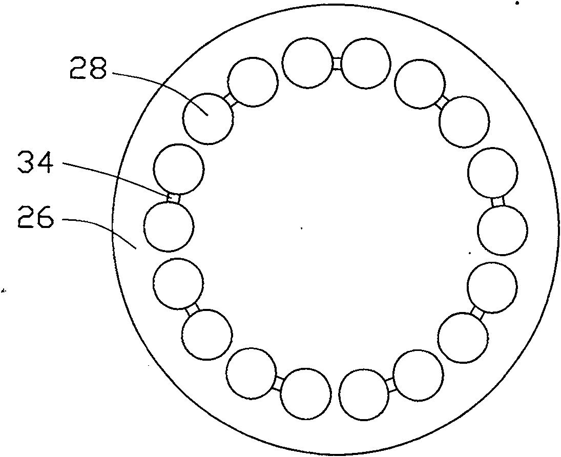
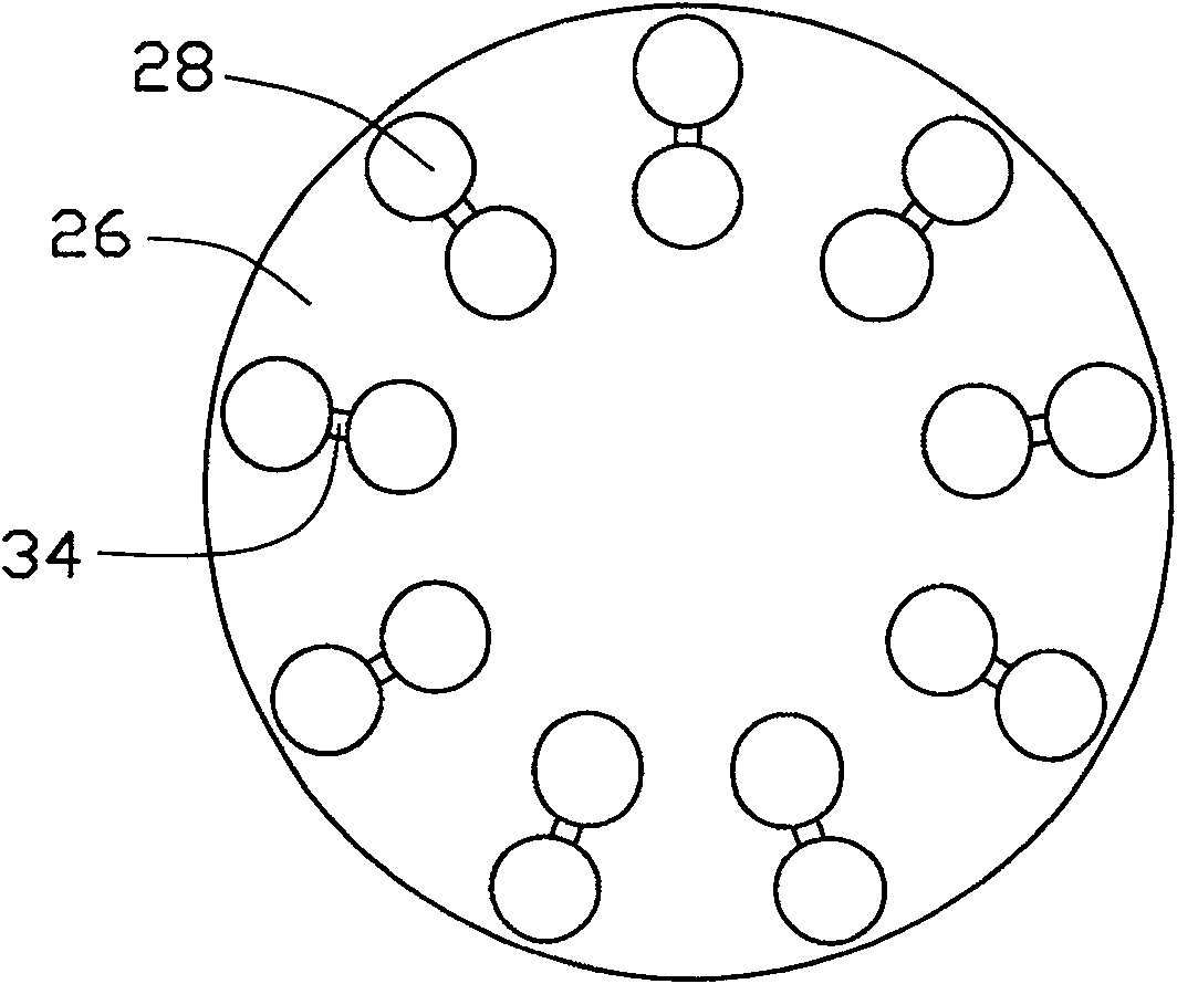
[0015] see figure 1 , is the sputtering device 200 provided in this embodiment, which includes a sputtering chamber 21, and a cavity is formed inside it. In this embodiment, the sputtering chamber 21 is a cylindrical chamber. The sputtering chamber 21 is provided with a first sputtering target 22 , a second sputtering target 24 , a base turntable 26 and multiple pairs of carrying platforms 28 .

[0016] The first sputtering target 22 is fixed on the top of the sputtering chamber 21 and is opposite to the upper surface of the base turntable 26 inside the sputtering chamber 21 . The first sputtering target 22 is directly connected to the cathode of the sputtering power supply or grounded through a wire 401 .

[0017] The second sputtering target 24 is ...


PUM


Abstract

The invention relates to a sputtering device, which includes a sputtering cavity, and the sputtering cavity is provided with a first sputtering target, a second sputtering target, a base turntable and multiple pairs of bearing platforms. The first sputtering target is set opposite to the upper surface of the base turntable, and the second sputtering target is set around the base turntable. The base turntable is connected with a rotation device, and the rotation device is used to drive the base turntable to rotate around the center of the base turntable. The multiple pairs of bearing platforms are arranged on the upper surface of the base turntable, each pair of bearing platforms is connected by a connecting rod, and the connecting rod is connected with a driving device to drive the two bearing platforms connected by the connecting rod to rotate around the center point of the connecting rod. The present invention also relates to a sputtering method using the sputtering device. Using the sputtering device for sputtering is simple and convenient to operate, and can uniformly coat a plurality of irregular-shaped workpieces at the same time, effectively improving the sputtering production of irregular-shaped workpieces. Efficiency, in order to achieve the purpose of mass production.

Description

technical field [0001] The present invention relates to a sputtering device and a sputtering method, in particular to a sputtering device suitable for sputtering workpieces with irregular shapes and a sputtering method using the sputtering device. Background technique [0002] Sputtering is a thin film physical vapor deposition technology. With the development of electronic technology and vacuum technology, it has been widely used in the production of various metal and non-metal film layers in industry. The principle of sputtering is to use high-energy plasma generated by glow discharge or ion beam to hit the target in a vacuum environment, and atoms are knocked out of the target by momentum transfer and deposited on the substrate to form a thin film. [0003] In mobile phone camera modules, in order to shield electromagnetic interference, a layer of metal, such as stainless steel or metal copper, is often plated on the lens mount by sputtering technology to prevent noise fr...

Claims


Application Information

Patent Timeline
Patent Type & Authority Patents(China)
IPC IPC(8): C23C14/34C23C14/54
Inventor 颜士杰
Owner HONG FU JIN PRECISION IND (SHENZHEN) CO LTD
Why Eureka
Try Eureka