Flat panel display with dual forked type side controlled cathode emission structure, and fabricating technique

A flat-panel display and cathode emission technology, which is applied in the manufacture of cold cathodes, cathode ray tubes/electron beam tubes, control electrodes, etc., can solve the problems of electrical breakdown, low emission efficiency of carbon nanotube cathodes, and low brightness of display devices , to achieve large-scale production that is conducive to commercialization, promote the development of high integration, and increase the effect of electron emission area

Inactive Publication Date: 2009-11-18
ZHONGYUAN ENGINEERING COLLEGE
View PDF4 Cites 0 Cited by
  • Summary
  • Abstract
  • Description
  • Claims
  • Application Information

AI Technical Summary

Problems solved by technology

Due to the constraints of the grid structure manufacturing process and manufacturing materials, these displays generally have disadvantages such as excessively high gate voltage, low brightness of the display device, and low emission efficiency of the carbon nanotube cathode. The impact of the cathode on the display image quality cannot be ignored
Since the insulating material between the grid structure and the carbon nanotube cathode structure has a certain insulation level, once the limit is exceeded, electrical breakdown will occur. Therefore, reducing the distance between the two to reduce the grid operating voltage is subject to limited to a certain extent
Since the electron beam emitted from the carbon nanotube cathode can only bombard the phosphor layer after passing through the grid structure, the emission area of ​​the carbon nanotube cathode cannot be made larger, otherwise it is easy to cause the grid to go out of control, which means that the carbon The effective electron emission area of ​​the nanotube cathode is fixed, which limits the further improvement of the display brightness of the device

Method used


Image

  • Flat panel display with dual forked type side controlled cathode emission structure, and fabricating technique
  • Flat panel display with dual forked type side controlled cathode emission structure, and fabricating technique
  • Flat panel display with dual forked type side controlled cathode emission structure, and fabricating technique

Examples


Embodiment Construction

[0039] The present invention will be further described below with reference to the drawings and embodiments, but not limited to these embodiments.

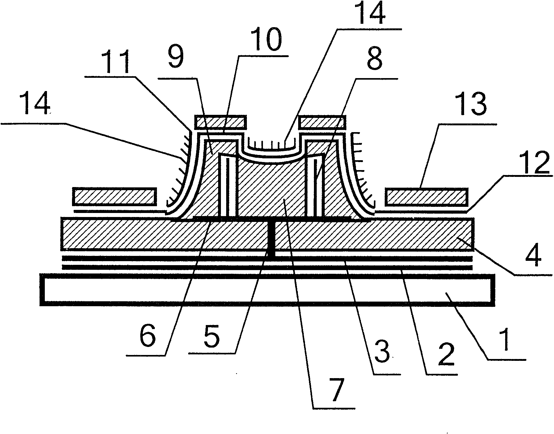
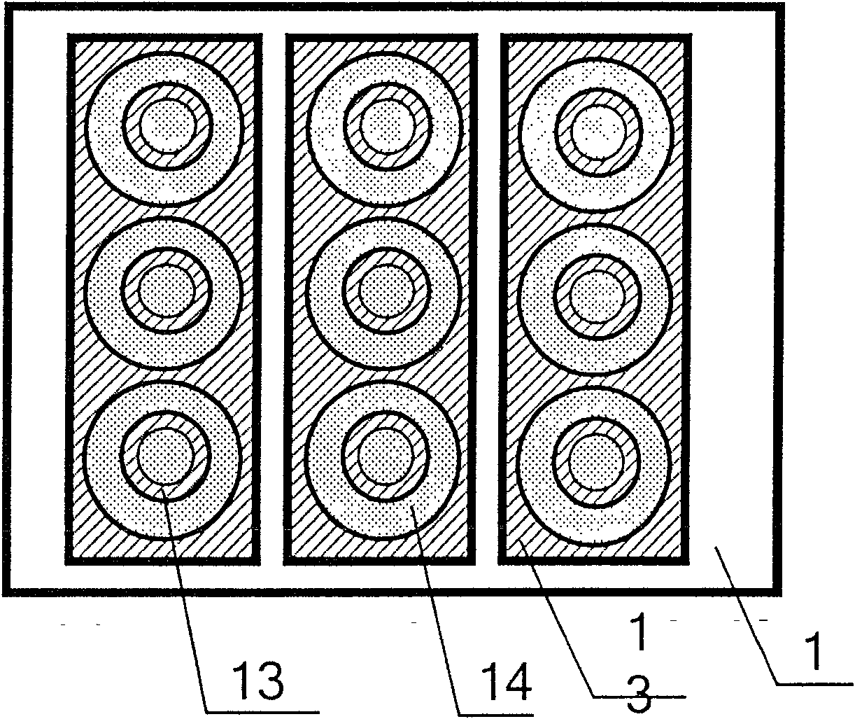
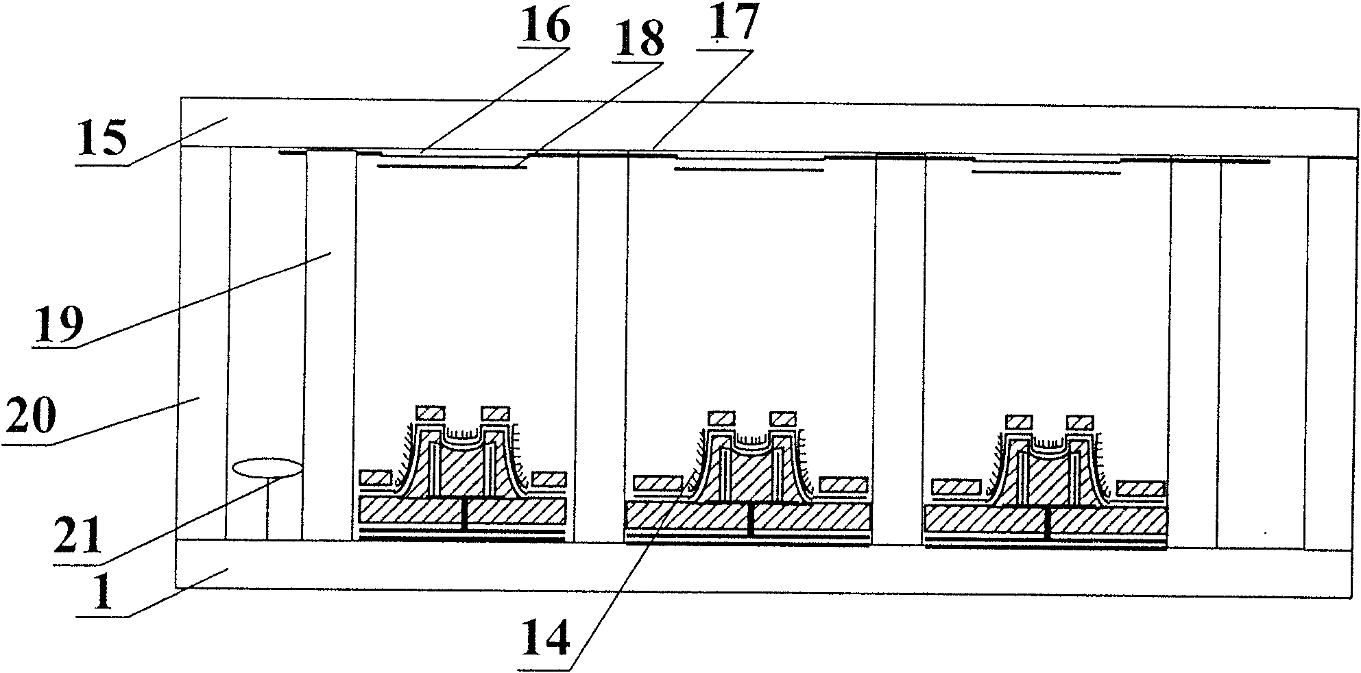
[0040] The flat-panel display with a bifurcated side-controlled cathode emission structure includes a sealed vacuum chamber composed of an anode glass panel [15], a cathode glass panel [1] and surrounding glass frames [20]; There is an anode conductive layer [16] and a phosphor layer [18] prepared on the anode conductive layer on the anode glass panel; there are grid lead layer [3], carbon nanotubes [14] and bifurcated type on the cathode glass panel Side-controlled cathode emission structure; support wall structure [19] and getter attachment element [21] between the anode glass panel and the cathode glass panel.

[0041] The bifurcated side-controlled cathode emitter structure includes a cathode glass panel [1], an insulating layer [2], a gate lead layer [3], a gate riser layer [4], a gate extension line layer [5], Grid control ...


PUM


Abstract

The invention relates to a double-fork type side-controlled cathode emission flat-panel display and its manufacturing process, including a sealed vacuum chamber composed of an anode glass panel, a cathode glass panel and surrounding glass frames; an anode set on the anode glass panel A conductive layer and a phosphor layer prepared on the anode conductive layer; a support wall structure and an accessory component of a getter between the anode glass panel and the cathode glass panel; a grid lead layer, carbon nanotubes and Bifurcated side-controlled cathode emission structure; it can further enhance the control function and control efficiency of the gate structure, improve the electron emission area and emission efficiency of the carbon nanotube cathode, and has the advantages of stable and reliable manufacturing process, simple manufacturing process, low manufacturing cost, and structural The advantage of simplicity.

Description

technical field [0001] The invention belongs to the fields of flat panel display technology, microelectronic science and technology, vacuum science and technology, and nano science and technology, and relates to device fabrication of flat panel field emission displays, in particular to carbon nanotube cathodes. The device manufacturing aspect of the flat panel field emission display particularly relates to a flat panel display with a double-fork type side-controlled cathode emission structure and its manufacturing process. Background technique [0002] The carbon nanotube field emission display is a new type of flat display device, which uses carbon nanotubes as the cathode material to replace the thermal electron gun in the traditional cathode ray tube display, so that there is no delay time and the response speed is faster. The electrons emitted from the cathode of the carbon nanotube accelerate to the anode under the action of the high voltage of the anode, and bombard th...

Claims


Application Information

Patent Timeline
Patent Type & Authority Patents(China)
IPC IPC(8): H01J31/12H01J31/15H01J29/02H01J29/04H01J1/304H01J1/46H01J9/02H01J9/00
Inventor 李玉魁
Owner ZHONGYUAN ENGINEERING COLLEGE
Why Eureka
Try Eureka