
Recovery method and device for cell update procedure in cell-DCH state

A technology for updating programs and base stations, which is applied in wireless communication, communication between multiple stations, and data exchange through path configuration. The effect of power consumption

Inactive Publication Date: 2009-12-02
L2 MOBILE TECH LLC
View PDF3 Cites 2 Cited by
  • Summary
  • Abstract
  • Description
  • Claims
  • Application Information

AI Technical Summary

Problems solved by technology

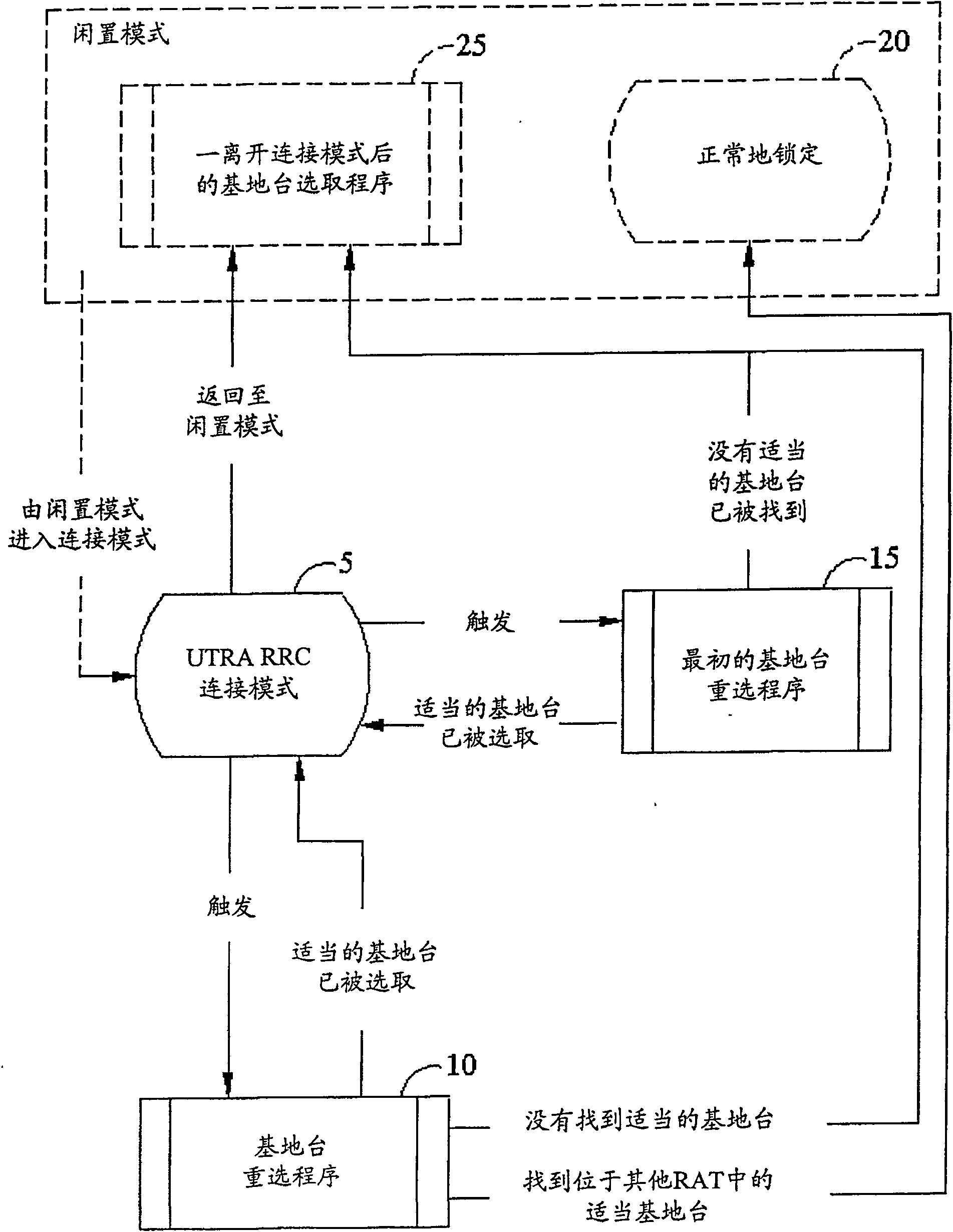
[0008] However, when the mobile device is in the CELL_DCH state, due to a radio link failure or an error that cannot be repaired by RLC, there are many undefined or unclear situations in the base station update procedure that is started.

Method used


Image

  • Recovery method and device for cell update procedure in cell-DCH state
  • Recovery method and device for cell update procedure in cell-DCH state
  • Recovery method and device for cell update procedure in cell-DCH state

Examples


Embodiment Construction

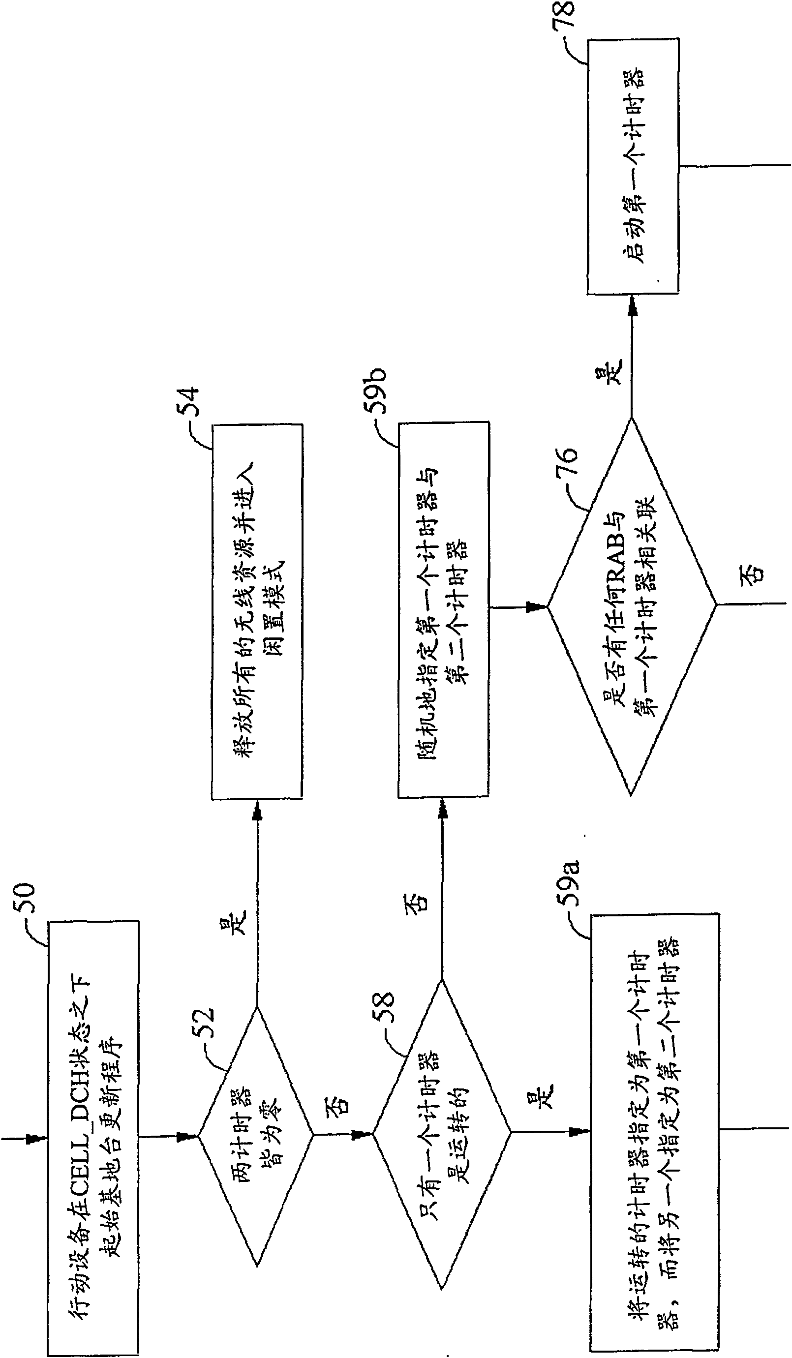
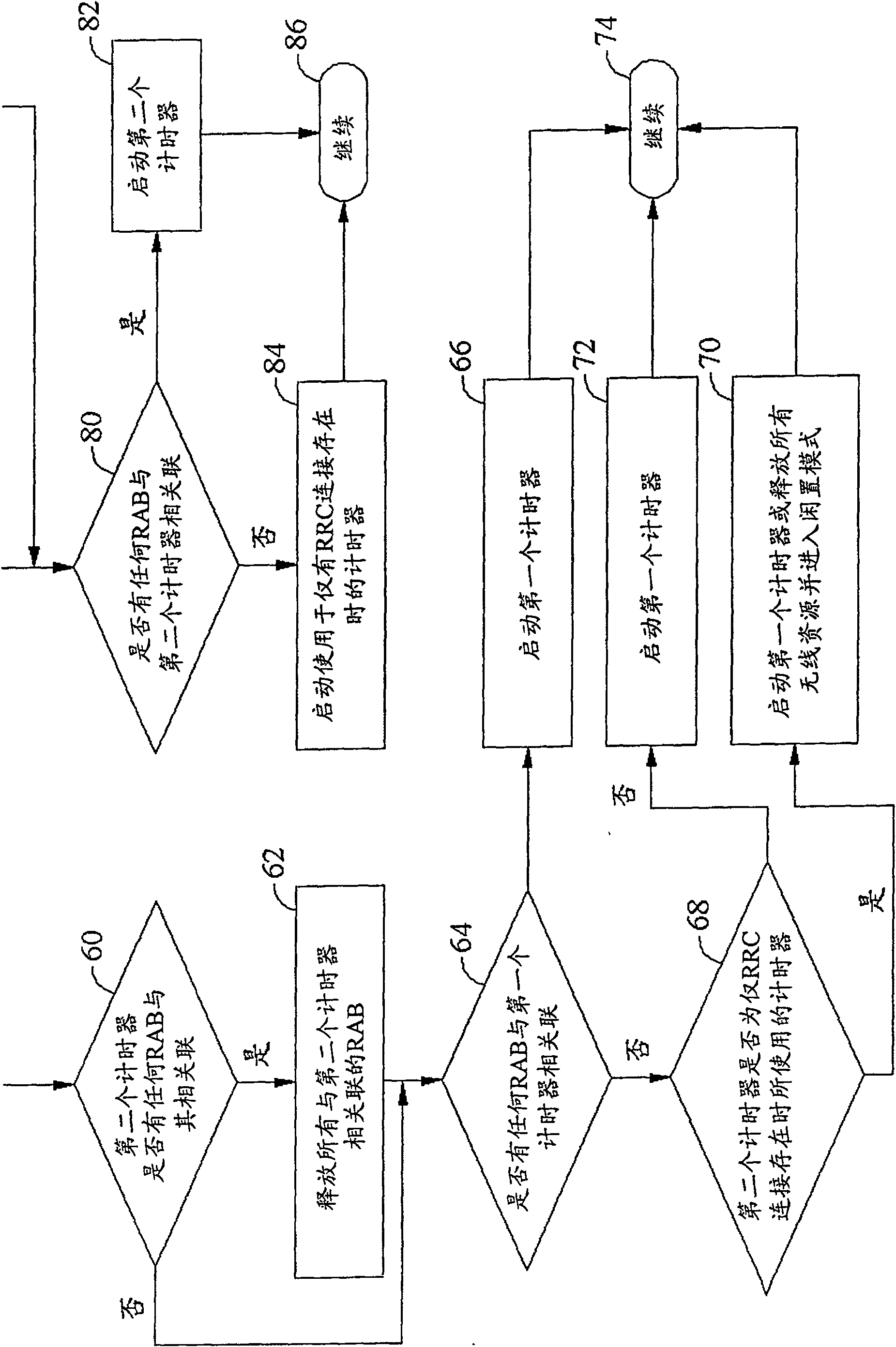
[0018] The present invention proposes an enhanced procedure so that the mobile device can handle radio link failure or RLC unrecoverable errors in the CELL_DCH state. Figure 2a and Figure 2bIt is a logic flow chart of the present invention. Once the mobile device starts the base station update procedure under the CELL_DCH state, step 50, the program proposed by the present invention will pass through the stored value of the two timers of checking T314 and T315 (T314=T315=0), step 52, to know Whether the two timers T314 and T315 are not running (not running); when the condition of T314=T315=0 is established, the mobile device will release all wireless resources and enter the idle mode, step 54 . Next, the program checks in step 58 if only one timer is running. When it is true, the program designates the running timer as the first timer and the non-running timer as the second timer, step 59a. On the other hand, if both timers are active, the program randomly designates one ...


PUM


Abstract

This invention provides an enhancement to the current mechanism used to make mobile device enter idle mode if a suitable cell could not be found and avoid unnecessary power consumption.

Description

technical field [0001] The present invention relates to a recovery method and device for wireless communication, in particular to a recovery method and device after connection interruption. Background technique [0002] Once a mobile device is turned on, it will search, find and select a base station in the selected public land mobile network (PLMN, public landmobile network), and then turn its control channel to and lock the base station. As long as the mobile device is powered on, base station selection and reselection will continue. In particular, when it moves between multiple base stations, it is unavoidable that the mobile device must interrupt communication with the base station with a weaker signal and reconnect with another base station with a better signal in order to have a better signal. Excellent signal quality. According to the connected mode radio measurement and the cell reselection criteria, the cell reselection procedure of the mobile device includes sele...

Claims


Application Information

Patent Timeline
IPC IPC(8): H04W52/02H04L12/28H04B7/26H04L12/56H04W72/00H04W76/06
CPCH04W76/068H04W72/00H04W52/0258Y02B60/50H04W76/38Y02D30/70H04W36/04H04W52/02
Inventor 陈欢跃
Owner L2 MOBILE TECH LLC
Learn More