Method of manufacturing spectacle lens

A manufacturing method and technology for spectacle lenses, which are applied in the directions of manufacturing tools, glasses/goggles, glasses/protective glasses, etc., can solve problems such as difficulty in sharpness adjustment, positioning control and marking accuracy, and machining axis offset, and achieve easy identification. , The effect of suppressing positioning errors and improving workability

Inactive Publication Date: 2009-12-09
HOYA CORP
View PDF9 Cites 1 Cited by
  • Summary
  • Abstract
  • Description
  • Claims
  • Application Information

AI Technical Summary

Problems solved by technology

In this case, after processing one side, the lens is removed from the lens holder, the other side is mounted on the processing jig, and after the optical information is inspected again, it must be fixed on the processing jig , so the method of coloring and marking semi-finished lenses requires a lot of time for power inspection or optical layout inspection
In addition, these power inspections and optical layout inspections require high measurement technology and proficiency because the lens itself is transparent and has curvature. If the inspection accuracy is poor, it will cause many problems such as machining axis deviation.
[0011] In addition, when using a laser marking device for a plastic lens, there are problems such as adjustment of marking definition, positioning control, and maintenance of marking accuracy due to the curved surface of the lens.

Method used


Image

  • Method of manufacturing spectacle lens
  • Method of manufacturing spectacle lens
  • Method of manufacturing spectacle lens

Examples


Embodiment Construction

[0075] Preferred modes for carrying out the present invention will be described below with reference to the drawings.

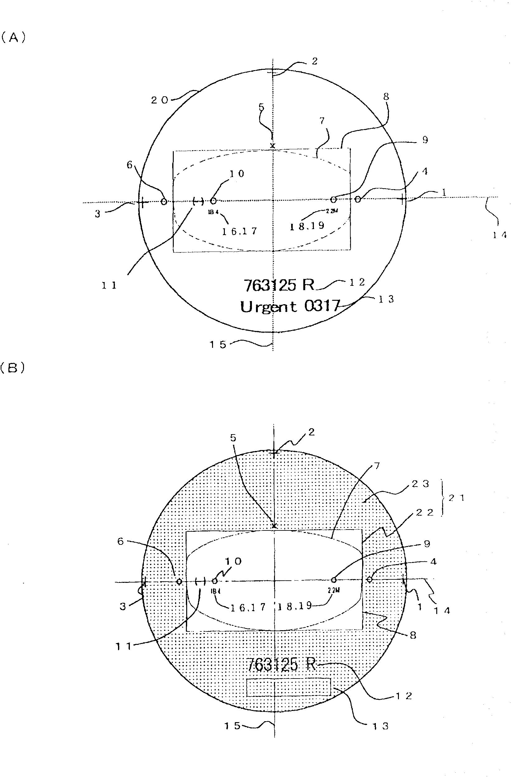
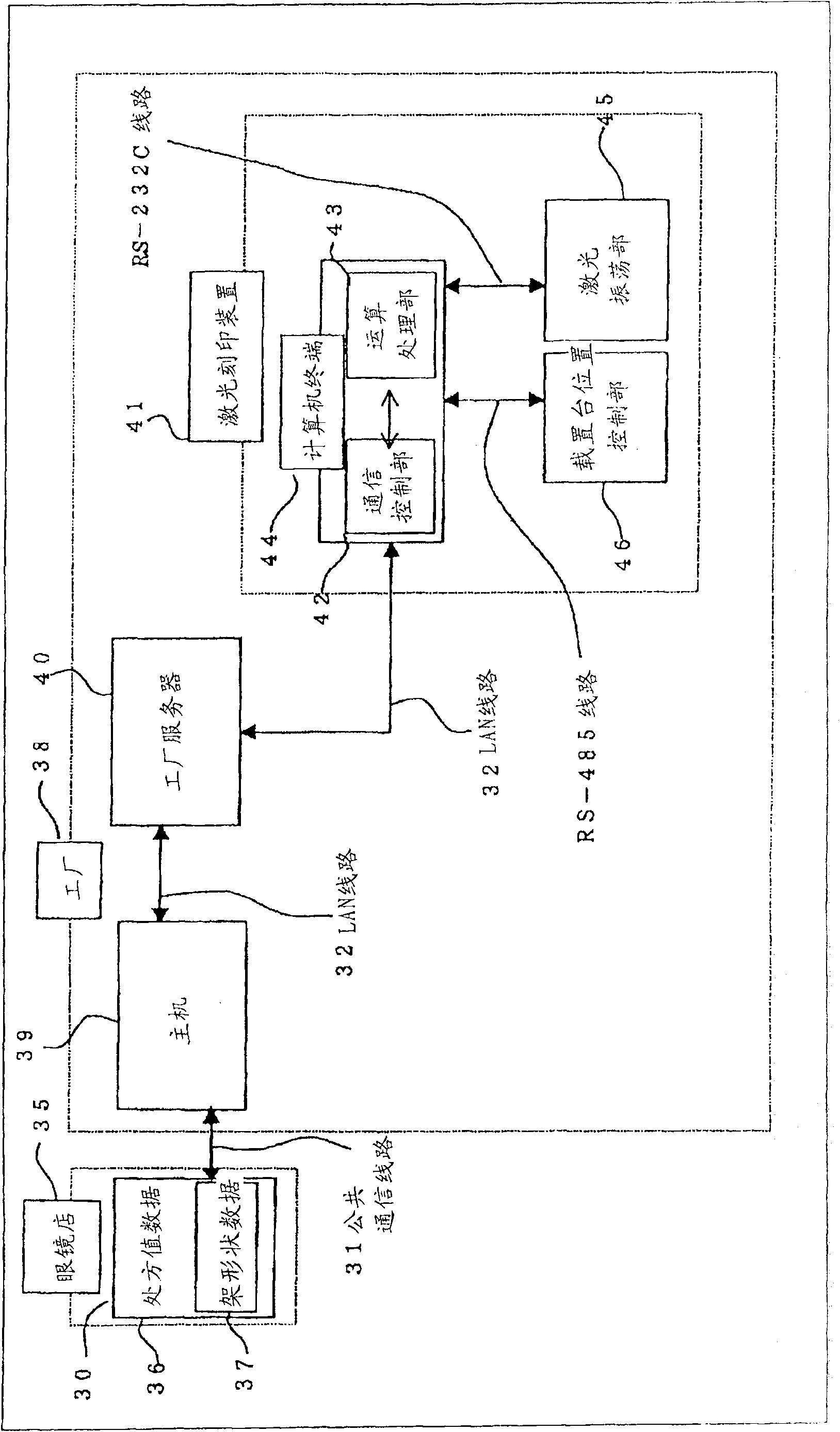
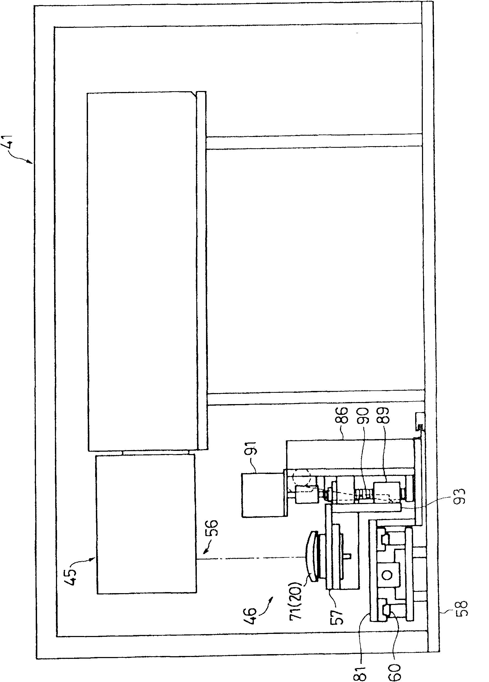
[0076] figure 1 It is a figure which shows the progressive-power lens in which various relevant information was imprinted in one Example of the spectacle lens of this invention. figure 2 It is a figure which shows the outline of the spectacle lens manufacturing system which implements one Example of the spectacle lens manufacturing method of this invention, and concretely demonstrates centering on a laser marking system.

[0077] exist figure 1 In this progressive power lens 20 (hereinafter referred to as the lens 20 ), spectacle lens-related information, spectacle frame-related information, prescription value and layout-related information, and manufacturing-related information are engraved.

[0078] Spectacle lens-related information includes, for example, product information 11 for specifying a supplier and a product name of the lens 20 , refractive ind...


PUM


Abstract

A manufacturing method of a spectacle lens improving a manufacturing yield and a production efficiency is provided. The manufacturing method of the spectacle lens in which necessary information for a frame machining of a spectacle lens (progressive-power lens 20) including spectacle rim related information is obtained, and both surfaces of a convex surface and a concave surface are edge / polish machined from a spectacle lens blanks. When the convex surface or the concave surface is polish machined, and thereafter, the next surface is machined, the spectacle rim related information and layout information of the edge machining are obtained, and first provisional reference position marks 1 to 3 and second provisional reference position marks 4 to 6 guiding a geometrical horizontal reference and a geometrical perpendicular reference of the lens are inscribed at positions outside of an edge shape 111 as identification marks for the machined surface being polished as a provisional reference marking process, an optical layout is performed for the surface to be machined next based on these provisional reference position marks to perform a lens block to a lens machining tool.

Description

technical field [0001] The present invention relates to a method of manufacturing ophthalmic lenses for which imprinting is carried out. Background technique [0002] In recent years, an edge-polished lens supply system in which lens manufacturers supply edge-polished lenses to optical shops is expanding. In this system, a lens manufacturer receives mosaic information including frame information selected by a customer from an optician online, sets processing conditions based on the mosaic information, implements edge polishing, and supplies the edge-polished lenses to the optician. [0003] Patent Document 1 proposes improvement of marking performed in these processing steps for the purpose of improving manufacturing yield. [0004] In addition, the types of existing markings on spectacle lenses are as follows, there are markings usually called hidden markings (marks with lens manufacturers, optical information of lenses, layout information, etc.) attached to commercially a...

Claims


Application Information

Patent Timeline
Patent Type & Authority Patents(China)
IPC IPC(8): B24B13/00G02C13/00G02C7/02B24B13/005B24B13/06
CPCB29D11/00951B24B9/148B24B9/146B24B13/0055B29D11/00942B29D11/00317
Inventor 秋山久则西冈正志新井三千男
Owner HOYA CORP
Why Eureka
Try Eureka