Fuel injection valve

The technology of a fuel injection valve and a fuel injection device is applied in the field of the injection valve of the fuel injection device of an internal combustion engine to achieve the effects of ensuring work, low temperature and large structural volume

Inactive Publication Date: 2009-12-09
ROBERT BOSCH GMBH
View PDF9 Cites 0 Cited by
  • Summary
  • Abstract
  • Description
  • Claims
  • Application Information

AI Technical Summary

Problems solved by technology

When the internal combustion engine tries to start again, this results in: the stroke movement of the actuator is no longer transmitted to the valve needle and the fuel injection valve no longer operates

Method used


Image

  • Fuel injection valve
  • Fuel injection valve
  • Fuel injection valve

Examples


Embodiment Construction

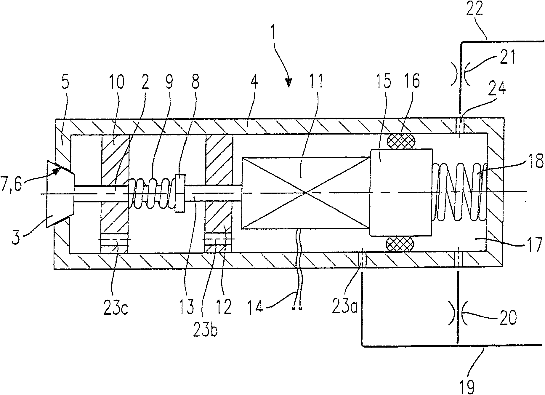
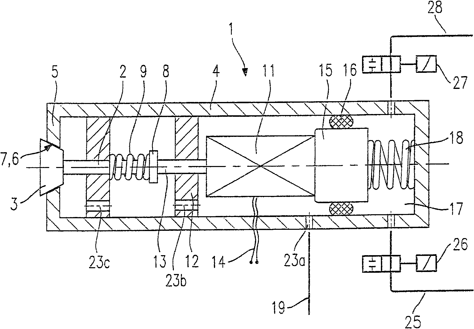
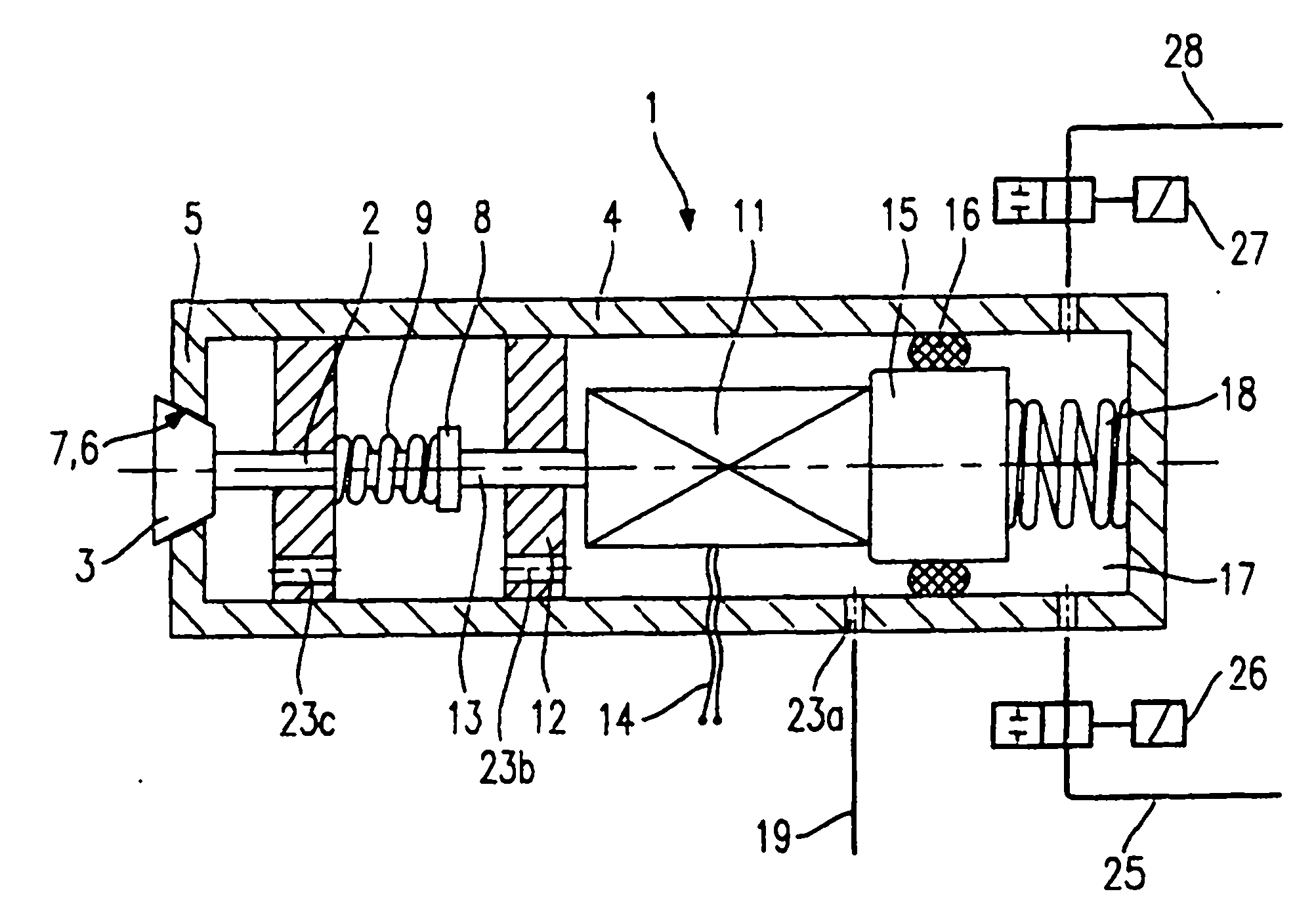
[0025] figure 1 A schematic sectional view is shown schematically as a schematic diagram of a fuel injector 1 . This is a fuel injector 1 with an outwardly openable valve needle 2 which is connected to a valve closure 3 . A valve seat carrier 5 integrally formed or formed integrally with the valve body 4 has a valve seat surface 6 which forms a sealing surface 7 with the valve closure part 3 . Valve needle 2 has a spring stop 8 on which valve spring 9 is supported. The second end of the valve spring 9 bears against a guide sleeve 10 for the valve needle 2 . The valve spring 9 exerts a preload force on the valve needle 2 via the spring stop 8 , which forces the valve closure part 3 against the sealing seat surface 6 .

[0026] The actuator 11 is connected to an actuator plunger 13 guided in the spacer 12 . The actuator 11 can be powered via the connection line 14 . At the end of the actuator 11 facing away from the sealing surface 6 , the actuator 11 is connected to a pres...


PUM


Abstract

A fuel injection valve (1), especially for fuel injection systems for internal combustion engines, has a piezoelectric or magnetostrictive actuator (11), which actuates a The valve closure (3) on (2), which cooperates with a valve seat surface to form a sealing mating surface (7), and has a hydraulic balance chamber (17). A pressure piston (15) interacts with a hydraulic balancing chamber (17) and the hydraulic balancing chamber is filled with hydraulic fluid via a hydraulic fluid inlet (25). The actuator (11) is arranged between the pressure piston (15) and the valve needle (2) and can move on the axis of the valve needle (2) and the pressure piston (15).

Description

technical field [0001] The invention relates to a fuel injection valve, in particular to an injection valve for a fuel injection device for an internal combustion engine. Background technique [0002] EP 0 477 400 A1 discloses a device for adaptive mechanical tolerance compensation acting in the travel direction for a piezoelectric actuator travel converter of an injection valve of an internal combustion engine. The actuator acts on an active piston which is connected to the hydraulic chamber and, by increasing the pressure in the hydraulic chamber, moves an output piston which moves a mass to be driven and positioned. The mass to be driven is, for example, the valve needle of a fuel injection valve. Wherein the hydraulic chamber is filled with hydraulic fluid. When the actuator is deflected and in the event of compression of the hydraulic fluid in the hydraulic chamber, a small fraction of the hydraulic fluid escapes with a defined leakage rate. Hydraulic fluid is replen...

Claims


Application Information

Patent Timeline
Patent Type & Authority Patents(China)
IPC IPC(8): F02M51/06F02M59/46F02M61/16F02M51/00F02M61/08F02M63/00
CPCF02M61/08F02M61/167F02M51/0603F02M2200/21
Inventor 乌韦·利斯科
Owner ROBERT BOSCH GMBH
Why Eureka
Try Eureka