
Digital storage oscillograph with very high waveform capturing rate

A waveform capture rate and digital storage technology, applied in the direction of digital variable display, etc., can solve the problems of not being able to meet the requirements of real-time test applications, lower test efficiency, and insufficient waveform capture rate, so as to increase the probability of transient abnormal signals and improve Test efficiency and the effect of improving the waveform capture rate

Active Publication Date: 2009-12-16
UNI TREND TECH (CHINA) CO LTD
View PDF6 Cites 0 Cited by
  • Summary
  • Abstract
  • Description
  • Claims
  • Application Information

AI Technical Summary

Problems solved by technology

Therefore, 99% of the waveform details will be missed during the blind time, and the waveform capture rate is insufficient, which greatly reduces the test efficiency. In many cases, it cannot meet the requirements of real-time test applications.

Method used


Image

  • Digital storage oscillograph with very high waveform capturing rate
  • Digital storage oscillograph with very high waveform capturing rate
  • Digital storage oscillograph with very high waveform capturing rate

Examples


Embodiment Construction

[0017] The following describes preferred specific embodiments of the present invention in conjunction with the accompanying drawings. It is to be noted that similar components are given similar reference numerals even though they appear in different drawings. In the following description, when a detailed description of known functions and designs employed may obscure the subject matter of the present invention, these descriptions will be omitted here.

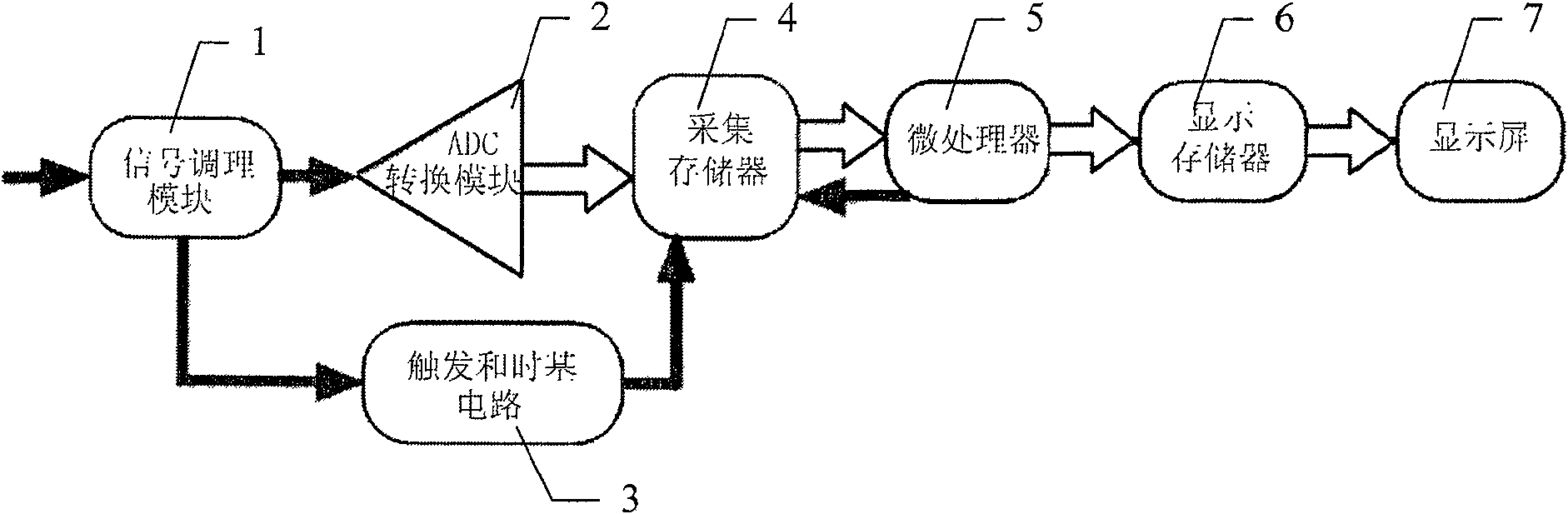
[0018] figure 1 It is a block diagram of a traditional digital storage oscilloscope. In the figure, after the input signal is conditioned by the signal conditioning module 1, the output amplitude is within a certain range and is suitable for the ADC conversion module 2 to perform data sampling. Under the control of the trigger and time base circuit 3, the waveform data sampled by the ADC conversion module 2 Send it to the cache in the acquisition memory 4.

[0019] After completing a waveform data collection, the microproces...


PUM


Abstract

The invention discloses a digital storage oscilloscope with a very high waveform capture rate. The input test signal is conditioned and sent to an ADC conversion module for sampling, and is sent to the acquisition memory cache under the control of a trigger and time base circuit; after a waveform acquisition is completed, The data collected by the parallel coprocessor is mapped to the waveform dot matrix data corresponding to the dot matrix of the display screen. After the mapping is completed, a new round of collection and mapping is restarted; at the same time, the microprocessor performs management work. When the timing is refreshed, the display refresh control logic is started immediately, the waveform dot matrix data and the dot matrix data are automatically combined in the display memory, and the display of the display screen is updated. The present invention adopts the framework of signal waveform acquisition and processing in parallel with the microprocessor, so that the microprocessor can be separated from the heavy waveform processing and display, reducing the blind time, improving the waveform capture rate, and increasing the detection of transient abnormal signals. probability, improving the test efficiency.

Description

technical field [0001] The invention relates to a digital storage oscilloscope, in particular to a digital storage oscilloscope with a very high waveform capture rate Background technique [0002] With the development of digital signal processing technology, the research on time-domain signal analysis technology based on high-speed sampling is getting more and more in-depth, and the digital time-domain test instrument has also been developed rapidly. As a typical time-domain test instrument, digital storage oscilloscope has obtained widely used. [0003] The waveform capture rate is one of the important indicators for evaluating the performance of a digital storage oscilloscope. The so-called "waveform capture rate" refers to the number of waveforms captured and displayed by the digital oscilloscope per unit time. Insufficient waveform capture rate will make it impossible to find most transient and occasional signals, let alone signal jitter analysis and eye diagram analys...

Claims


Application Information

Patent Timeline
Patent Type & Authority Patents(China)
IPC IPC(8): G01R13/02
Inventor 曾浩张沁川邱渡裕滕志超
Owner UNI TREND TECH (CHINA) CO LTD
Learn More