Drive system and method for moving domain wall of ferromagnetic conduit

A drive system and magnetic domain wall technology, applied in the field of magnetic logic systems, can solve the problems of inconvenient magnetic fields

Inactive Publication Date: 2010-01-27
INGENIA TECH LTD (GB)
View PDF1 Cites 0 Cited by
  • Summary
  • Abstract
  • Description
  • Claims
  • Application Information

AI Technical Summary

Problems solved by technology

[0005] While rotating magnetic fields are very effective in pushing magnetic domain walls, having to generate such a field is inconvenient because relatively high currents and bulky coils usually have to be used
This poses a problem when used in portable devices, such as laptop computers and mobile phones, because in these applications, the power required to generate the rotating magnetic field is too large for the limited capacity of the battery. unbearable power consumption

Method used


Image

  • Drive system and method for moving domain wall of ferromagnetic conduit
  • Drive system and method for moving domain wall of ferromagnetic conduit
  • Drive system and method for moving domain wall of ferromagnetic conduit

Examples


Embodiment Construction

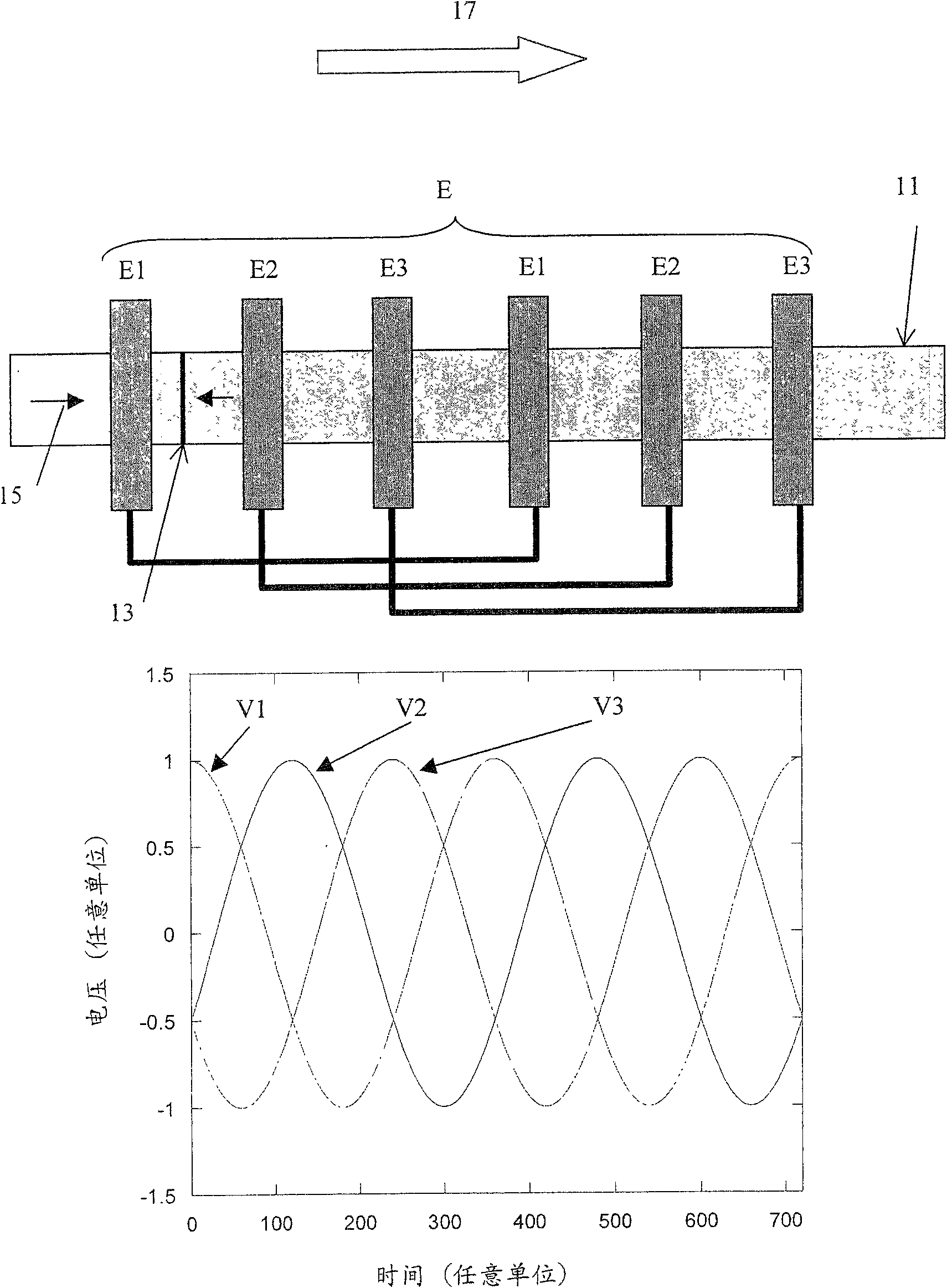
[0044] figure 1 is a specific example of the preferred situation, wherein three voltages are respectively applied to three different contact groups, each voltage has a phase difference of ±120° from the other two voltages, and the waveform of the voltages is a sine wave.

[0045] This figure is a schematic diagram of a typical submicron path of a ferromagnetic material (magnetic domain wall conduit). The figure shows a transported or moving magnetic domain wall (13) within the path, the direction of magnetization on both sides of which is indicated by arrows (15). Electrical connections or connectors (E) are formed in the magnetic domain wall conduits, connected in three different groups (E1, E2, E3). These three different groups are applied with three different voltages (V1, V2, V3), which are sinusoidal waveforms with a phase difference of ±120° from each other, such as figure 1 shown in the section below.

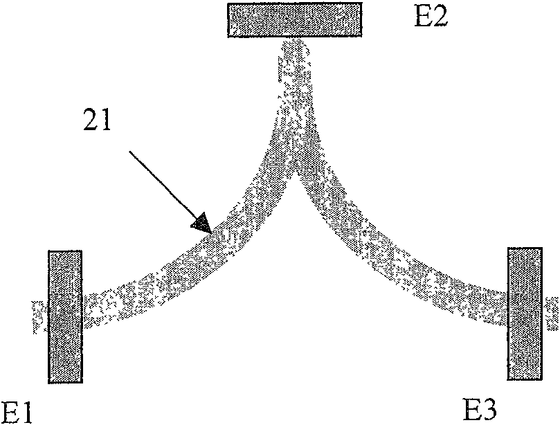
[0046] At the beginning of the first cycle, there is a net elect...


PUM


Abstract

A driving system and method to effect propagation of a magnetic domain wall through a ferromagnetic conduit are described, wherein oscillating electrical current is passed through the conduit from an oscillating current supply source via at least two electrical contacts adapted to make electrical connection with at least two spaced points on the conduit. A ferromagnetic conduit is described comprising an elongate ferromagnetic element formed as a continuous track of magnetic material capable of sustaining and propagating a domain wall, and such a driving system in serial array, preferably being further adapted to serve as a magnetic logic element by the provision of nodes and / or directional changes as a result of which logical functions may be processed.

Description

(1) Technical field [0001] The present invention relates to providing a drive system and method of moving magnetic domain walls through a conduit in a magnetic logic system, and to a magnetic logic system and method of operating such a magnetic logic system with the drive system. (2) Background technology [0002] A new system for digital logic is described in International Patent Application WO 02 / 41492 using magnetic conduits through which magnetic domain walls or solitons (solitons) can be formed along photolithographic techniques. The conduit is formed with a network of multiple monodomain particles interacting magnetostatically or with continuous tracks of submicron width ferromagnetic material. [0003] In traditional microelectronics digital logic. The two Boolean (logic) states "1" and "0" are signaled with high and low voltages. In the nanomagnetic logic scheme proposed in the aforementioned patent application, these two Boolean states are signaled by the directio...

Claims


Application Information

Patent Timeline
Patent Type & Authority Patents(China)
IPC IPC(8): G11C19/08H03K19/16
CPCG11C19/0808G11C19/0841H03K19/16G11C19/08H03K19/00H03K19/195
Inventor R·P·考波恩
Owner INGENIA TECH LTD (GB)
Why Eureka
Try Eureka