
Frequency-changing hydraulic elevator system

A technology of elevator system and hydraulic system, applied in the field of hydraulic elevator system, can solve the problems of speed shock, unsuitable leakage compensation, elevator vibration and shock, etc., to reduce speed shock and pressure shock, reduce pressure shock, and reduce speed shock. Effect

Active Publication Date: 2010-02-03
SHANGHAI MITSUBISHI ELEVATOR CO LTD
View PDF13 Cites 0 Cited by
  • Summary
  • Abstract
  • Description
  • Claims
  • Application Information

AI Technical Summary

Problems solved by technology

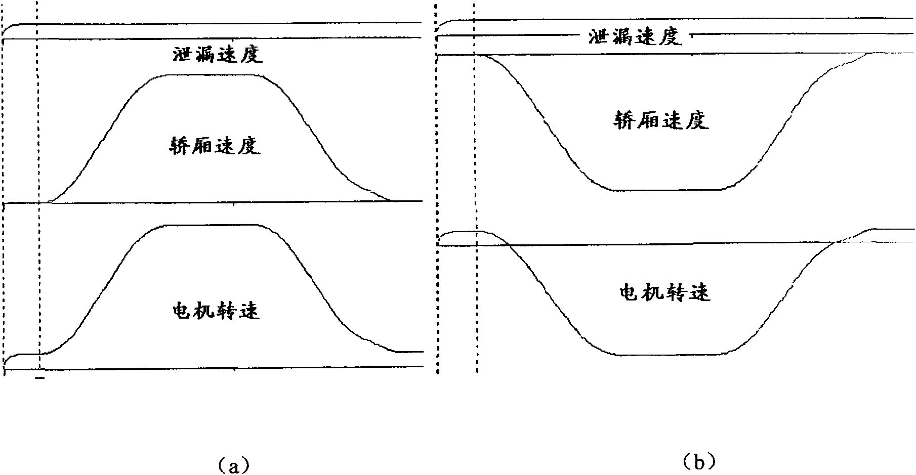
[0008] In all the disclosed technical schemes of hydraulic elevator systems using speed-regulating motors, there is a common problem, that is, due to oil leakage in the system, the rotational speed of the motor is not synchronized with the actual speed of the elevator. Vibration and shock of the elevator manifested in the start-up process
The method of indirectly compensating the oil leakage by the bias model only considers the speed shock at startup, but does not consider the pressure shock of the system, and the leakage compensation cannot be applied to changes in load, oil temperature, hydraulic pump processing error, etc.
Using the pressure regulation method for start-up compensation can provide higher accuracy, but pressure regulation is a dynamic process, in which the speed of the hydraulic pump changes continuously, and when the pressure balance point is reached, the output flow of the hydraulic pump may not be able to fully compensate Leakage will cause speed impact. In addition, when the frequency conversion device is working, the signal of the pressure transmitter is easily disturbed, so the reliability of only pressure regulation is not high.

Method used


Image

  • Frequency-changing hydraulic elevator system
  • Frequency-changing hydraulic elevator system
  • Frequency-changing hydraulic elevator system

Examples


Embodiment Construction

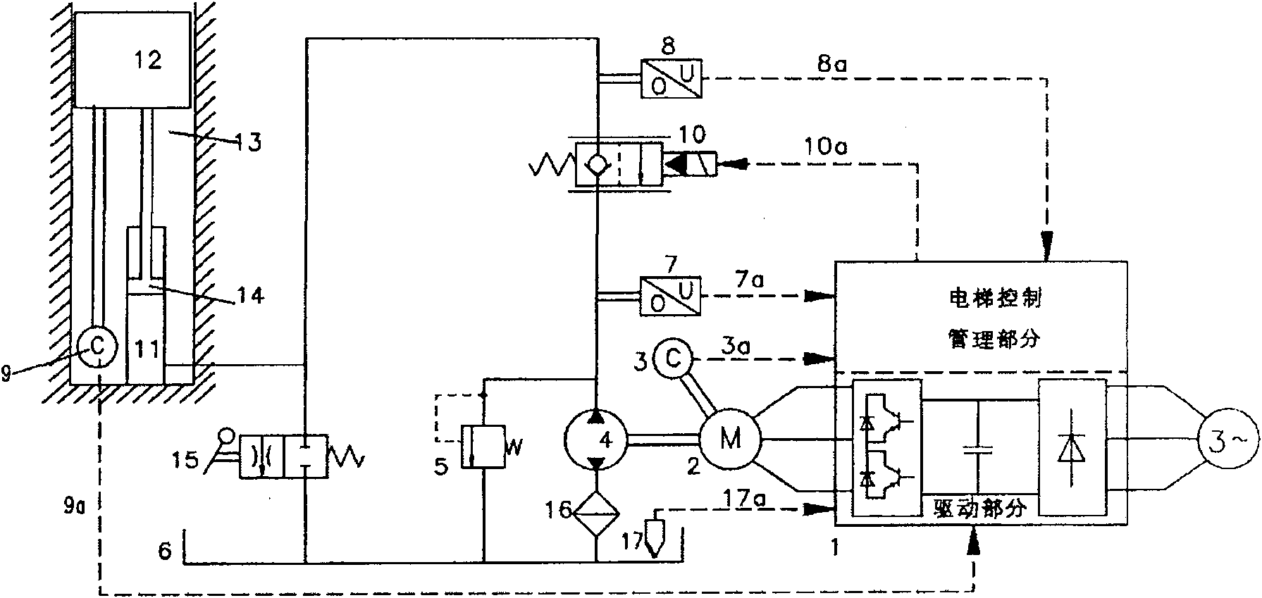
[0020] see figure 1 As shown, the hydraulic elevator system includes an elevator shaft 13, an oil cylinder 11 buried in the bottom pit of the elevator shaft 13, pressure oil injected into the oil cylinder 11, a piston 14 supported by the pressure oil, and a car fixed on the upper end of the piston 14. 12. Motor 2, hydraulic pump 4, elevator controller 1 connected to motor 2 and motor side encoder 3, solenoid valve 10 connected to hydraulic pump 4 and oil cylinder 11, used to detect the outlet oil pressure of hydraulic pump 4 A pressure transmitter 7, a second pressure transmitter 8 for detecting the oil pressure of the oil cylinder 11, a car side encoder 9 for measuring the speed of the car, and an oil temperature sensor 17 for measuring the oil temperature of the hydraulic system , and the overflow valve 5 connecting the hydraulic pump 4 and the oil tank 6, and the manual oil unloading valve 15 connecting the oil cylinder 11 and the oil tank 6.

[0021] The hydraulic pump 4 ...


PUM


Abstract

The invention discloses a frequency conversion hydraulic elevator system, consisting of a leakage measurement system, a leakage estimating system and a pressure adjusting system; wherein, the leakagemeasurement system consists of a first pressure transmitter, an oil temperature sensor, a motor side encoder and an elevator car side encoder; the practical leakage quantity of the hydraulic system isdirectly measured during the running process of the elevator; furthermore, corresponding leakage quantity is memorized according to the conditions of oil temperature and load during the measurement process; the leakage estimating system consists of a second pressure transmitter and an oil temperature sensor; leakage quantity parameters under the corresponding conditions of oil temperature and load memorized by the leakage measurement system are extracted, the leakage quantity of the hydraulic system is estimated and the leakage is compensated before the elevator is started; the pressure adjusting system consists of the first pressure transmitter and the second pressure transmitter; during the starting process of the elevator, the rotation speed of the hydraulic pump is adjusted graduallyso as to lead the oil pressure at the outlet of the hydraulic pump and the oil pressure in the oil cylinder to achieve balance. The frequency conversion hydraulic elevator system can reduce the speedimpact and pressure impact during the starting process of the frequency conversion hydraulic elevator and leads to stable and quick starting process.

Description

technical field [0001] The invention relates to a hydraulic elevator system, which is a drive motor driven by variable voltage and frequency conversion. Pressure balance, so as to achieve the smooth start of the elevator car frequency conversion hydraulic elevator system. Background technique [0002] The motor speed control system is applied to the hydraulic elevator system, which can greatly improve its efficiency, and is considered as an energy-saving hydraulic elevator system. A constant flow hydraulic pump provides pressure oil to the oil cylinder through a solenoid valve to move the car up and down. The above solenoid valve usually operates as a one-way stop valve to prevent safety accidents when the elevator goes down, but when the solenoid valve is electromagnetically excited, It can be reversed to make the elevator go down. Due to the weight of the car, the pressure oil in the oil cylinder and its pipeline is continuously under a certain oil pressure. When the ab...

Claims


Application Information

Patent Timeline
Patent Type & Authority Patents(China)
IPC IPC(8): B66B11/04B66B9/04
Inventor 黄维纲冯麟
Owner SHANGHAI MITSUBISHI ELEVATOR CO LTD
Learn More