
Hydraulic pressure elevator system

An elevator system, hydraulic technology, applied to elevators, hoists, transportation and packaging in buildings, etc., can solve the problems of speed shock, leakage compensation cannot be applied, elevator vibration and shock, etc., to reduce speed shock and pressure shock, Reduce the effect of speed shock and pressure shock

Inactive Publication Date: 2010-02-03
SUZHOU XINDA ESCALATOR ACCESSORIES
View PDF3 Cites 3 Cited by
  • Summary
  • Abstract
  • Description
  • Claims
  • Application Information

AI Technical Summary

Problems solved by technology

[0007] In all the disclosed technical schemes of hydraulic elevator systems using speed-regulating motors, there is a common problem, that is, due to oil leakage in the system, the rotational speed of the motor is not synchronized with the actual speed of the elevator. Vibration and shock of the elevator manifested in the start-up process
The method of indirectly compensating the oil leakage by the bias model only considers the speed shock at startup, but does not consider the pressure shock of the system, and the leakage compensation cannot be applied to changes in load, oil temperature, hydraulic pump processing error, etc.
Using the pressure regulation method for start-up compensation can provide higher accuracy, but pressure regulation is a dynamic process, in which the speed of the hydraulic pump changes continuously, and when the pressure balance point is reached, the output flow of the hydraulic pump may not be able to fully compensate Leakage will cause speed impact. In addition, when the frequency conversion device is working, the signal of the pressure transmitter is easily disturbed, so the reliability of only pressure regulation is not high.

Method used


Image

  • Hydraulic pressure elevator system

Examples


Embodiment Construction

[0013] The technical scheme of the invention will be described in detail below in conjunction with the drawings:

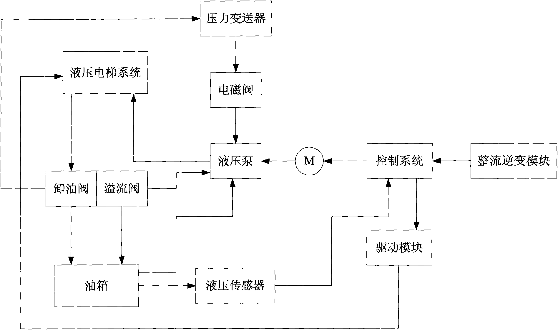
[0014] Such as figure 1 As shown, the hydraulic elevator system is characterized by including hydraulic elevator system, unloading valve, overflow valve, fuel tank, pressure transmitter, solenoid valve, hydraulic pump, hydraulic sensor, electric motor, drive module, control system and rectifier inverter Module, in which the rectifier and inverter module is connected in series with the control system, the motor, the hydraulic pump, and the hydraulic elevator system. The output of the control system is connected with the drive module, the hydraulic elevator system, the oil unloading valve, the oil tank, and the hydraulic sensor in series, and then returns to the control system. The output end of the overflow valve is connected to the hydraulic pump and the oil tank respectively, the output end of the oil tank is connected to the hydraulic pump, and the output end of th...


PUM


Abstract

The invention discloses a hydraulic pressure elevator system, which is characterized in that the system comprises a hydraulic pressure elevator system, an oil drain valve, an overflow valve, an oil box, a pressure transmitter, a solenoid valve, a hydraulic pressure pump, a hydraulic pressure sensor, an electric motor, a driving module, a control system and a rectification inversion module, whereinthe rectification inversion module is connected with the control system, the electric motor, the hydraulic pressure pump, the hydraulic pressure elevator system in series in order; an output end of the control system is connected with the driving module, the hydraulic pressure elevator system, the oil drain valve, the oil box and the hydraulic pressure sensor in series in order and then returns to the control system; an output end of the overflow valve is connected with the hydraulic pressure pump and the oil box respectively; an output end of the oil box is connected with the hydraulic pressure pump; and an output end of the oil drain valve is connected with the pressure transmitter, the solenoid valve and the hydraulic pressure pump in series in order. The hydraulic pressure elevator system has the advantage of smoother and faster start.

Description

Technical field [0001] The invention relates to the technical field of a hydraulic elevator system. Background technique [0002] In a normal hydraulic system, oil leakage is inevitable. Therefore, the speed of the motor is not synchronized with the actual speed of the car; that is, there is a hydraulic pump running at a low speed, but the car does not start. When the elevator runs according to the start command signal, problems of start-up vibration and uncomfortable feeling occur. [0003] The earliest method is to output oil in advance according to the corresponding leakage amount, or in other words, superimpose a bias model signal that starts the motor at a low speed but does not start the car and a model signal that drives the car, so that the leakage can be compensated. Start smoothly. [0004] According to this method, in order to reduce the start-up vibration, the bias model signal obtained is determined with reference to the leakage under a certain load and a certain tempe...

Claims


Application Information

Patent Timeline
Patent Type & Authority Applications(China)
IPC IPC(8): B66B9/04B66B1/04
Inventor 陈金云李革康莉
Owner SUZHOU XINDA ESCALATOR ACCESSORIES
Learn More