Transmitter structure for communications systems
A transmitter and signal gain technology, applied in transmission systems, communication between multiple stations, amplification control, etc., can solve intermodulation distortion, reduce nonlinearity, power consumption and other problems
- Summary
- Abstract
- Description
- Claims
- Application Information
AI Technical Summary
Problems solved by technology
Method used
Image
Examples
Embodiment Construction
[0036] Transmitter structure
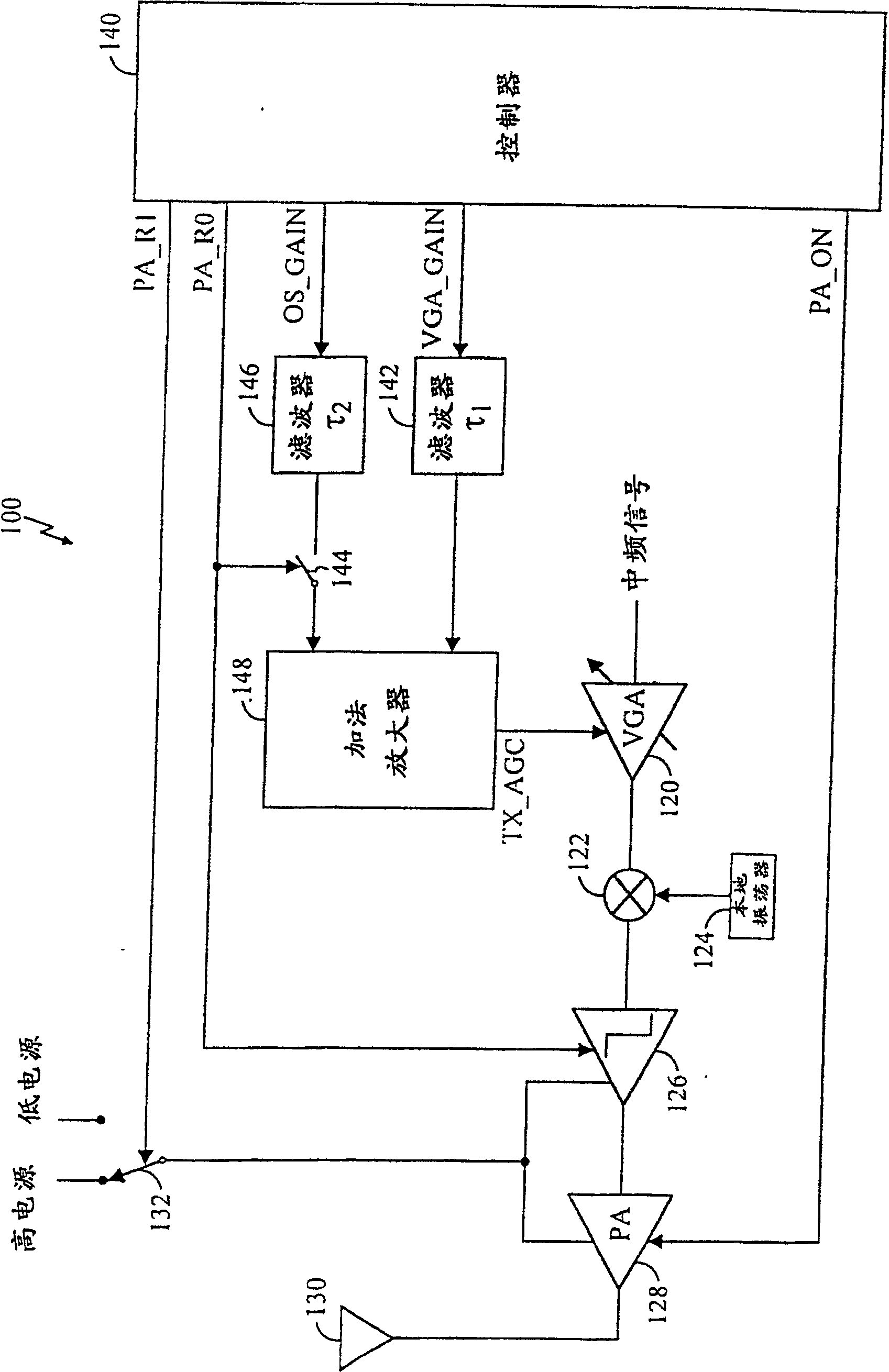
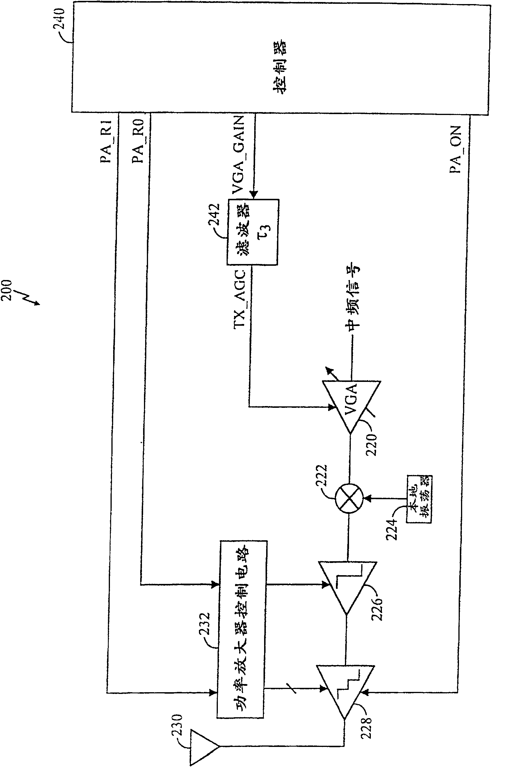
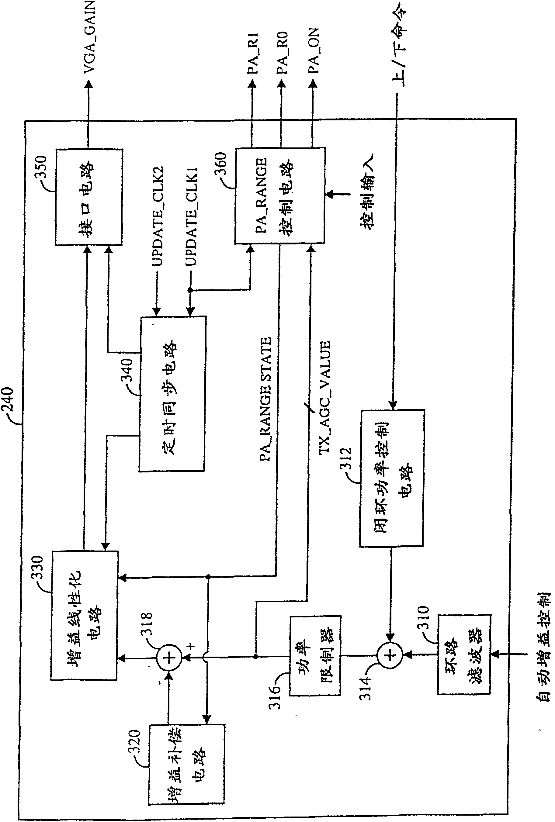
[0037] figure 1 A block diagram of an embodiment of a transmitter 100 of a communication system is shown. figure 1 The transmitter shown in can be used in a variety of applications, including cellular telephones, high-definition television (HDTV), cable television, and others. In the transmission path, the intermediate frequency (IF) signal is amplified by the variable gain amplifier (VGA) 120, and the sinusoidal signal from the local oscillator (LO) 124 is used by the mixer 122 to convert the frequency into a radio frequency (RF). ) 126 and buffered by a power amplifier (PA) 128 that drives antenna 130. Depending on the desired linearity, driver 126 and power amplifier 128 are coupled to a high supply (VDD_high) or a low supply (VDD_low) via a switch 132 controlled by a control signal PA_R1. The transmit chain of transmitter 100 includes elements in the transmit signal path (ie, from mixer 122 to antenna 130 ), but does not support circuitr...
PUM
 Abstract
Description
Claims
Application Information
 - R&D
- Intellectual Property
- Life Sciences
- Materials
- Tech Scout
- Unparalleled Data Quality
- Higher Quality Content
- 60% Fewer Hallucinations
Browse by: Latest US Patents, China's latest patents, Technical Efficacy Thesaurus, Application Domain, Technology Topic, Popular Technical Reports.
© 2025 PatSnap. All rights reserved.Legal|Privacy policy|Modern Slavery Act Transparency Statement|Sitemap|About US| Contact US: help@patsnap.com


