Supercharge Your Innovation With Domain-Expert AI Agents!

Transmitter architecture for communications system

A transmitter and signal technology, applied in transmission systems, communication between multiple stations, amplification control, etc., can solve problems such as reducing nonlinearity, power consumption, and reducing system performance.

Inactive Publication Date: 2009-10-14
QUALCOMM INC
View PDF8 Cites 3 Cited by
  • Summary
  • Abstract
  • Description
  • Claims
  • Application Information

AI Technical Summary

Problems solved by technology

[0005] In CDMA communication systems, non-linearity generation in the transmitter manifests itself as intermodulation distortion and degrades system performance
To reduce non-linearity, components in the transmit signal path are designed to operate within their linear range, resulting in large power consumption

Method used


Image

  • Transmitter architecture for communications system
  • Transmitter architecture for communications system
  • Transmitter architecture for communications system

Examples


Embodiment Construction

[0036] Transmitter structure

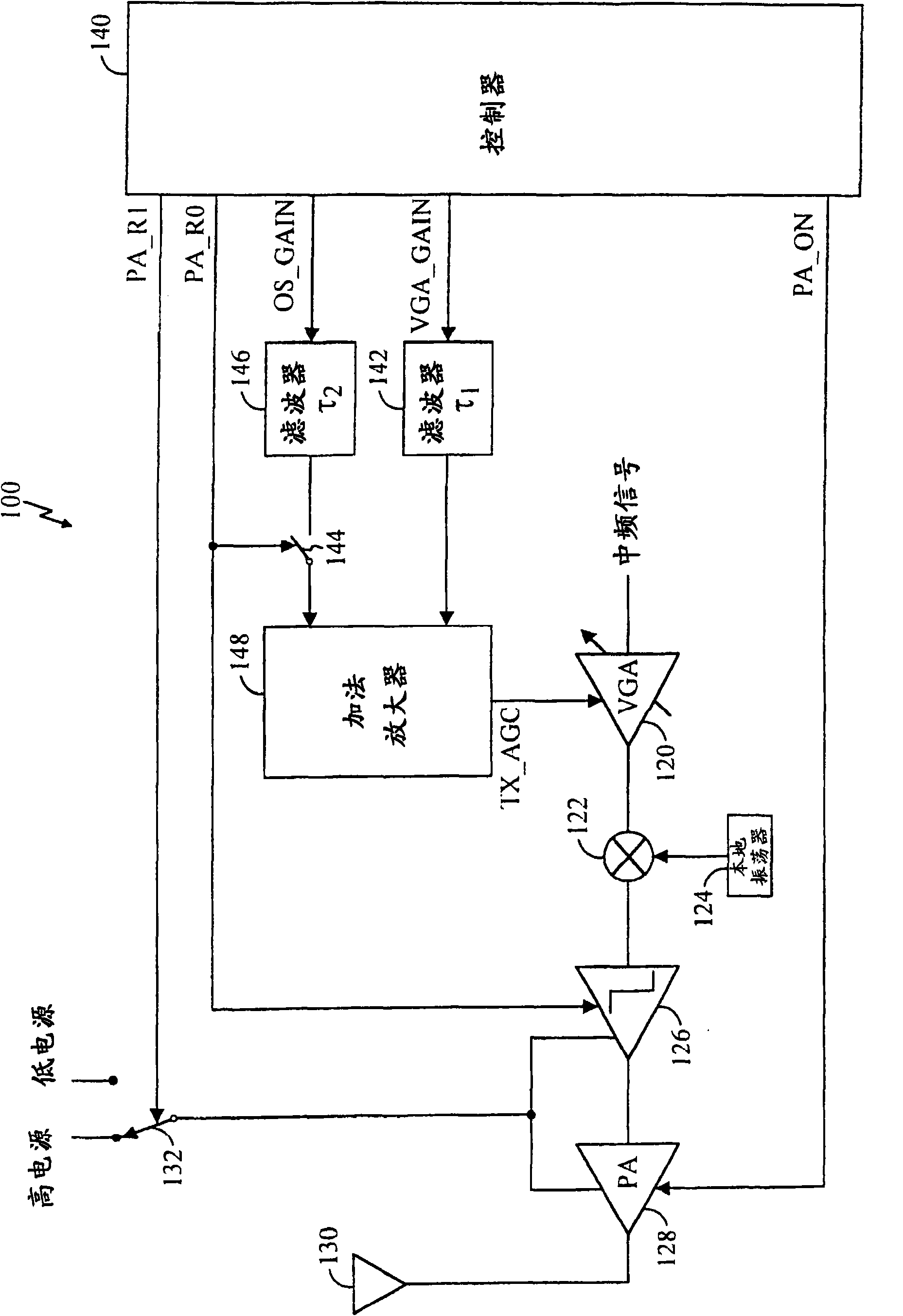
[0037] figure 1 A block diagram of an embodiment of a transmitter 100 of a communication system is shown. figure 1 The transmitter shown in can be used in a variety of applications, including cellular telephones, high-definition television (HDTV), cable television, and others. In the transmission path, the intermediate frequency (IF) signal is amplified by the variable gain amplifier (VGA) 120, and the sinusoidal signal from the local oscillator (LO) 124 is used by the mixer 122 to convert the frequency into a radio frequency (RF). ) 126 and buffered by a power amplifier (PA) 128 that drives antenna 130. Depending on the desired linearity, driver 126 and power amplifier 128 are coupled to a high supply (VDD_high) or a low supply (VDD_low) via a switch 132 controlled by a control signal PA_R1. The transmit chain of transmitter 100 includes elements in the transmit signal path (ie, from mixer 122 to antenna 130 ), but does not support circuitr...


PUM


Abstract

The invention relates to a transmitter architecture for a communications system having improved performance over conventional transmitter architectures. The improvements include a combination of the following: faster response time for the control signals, improved linearity, reduced interference, reduced power consumption, lower circuit complexity, and lower costs. For a cellular application, these improvements can lead to increased system capacity, smaller telephone size, increased talk and standby times, and greater acceptance of the product. Circuitry is provided to speed up the response time of a control signal. The control loop for various elements in the transmit signal path are integrated. A gain control mechanism allows for accurate adjustment of the output transmit power level. Control mechanisms are provided to power down the power amplifier, or the entire transmit signal path, when not needed. The gains of the various elements in the transmit signal path are controlled to reduce transients in the output transmit power, and to also ensure that transients are downward.

Description

[0001] This application is a divisional application of the invention patent application with the application number 200410056373.7, the application date is March 2, 2001, and the invention title is "Transmitter Structure of Communication System", and the said invention patent application is the application number 01808125.8 , A divisional application of another invention patent application with the filing date of March 2, 2001 and the invention title of "Transmitter Structure of Communication System". technical field [0002] This invention relates to electronic circuits in communication systems, and more particularly to transmitter structures providing improved performance. Background technique [0003] Various design considerations make the design of high performance transmitters challenging. For many applications, high performance is required to meet system specifications. High performance can be characterized by the linearity of the transmit signal path, wide dynamic ra...

Claims


Application Information

Patent Timeline
Patent Type & Authority Applications(China)
IPC IPC(8): H03G3/30H04B1/04H03G3/20H04B7/005H04B7/24
CPCH03F2203/7239H03G1/0088H03G3/3042H04B1/04
Inventor S·尤尼斯E·希米奇T·威尔伯恩张海涛D·菲利波维奇R·考夫曼林明宇
Owner QUALCOMM INC
Features
  • R&D
  • Intellectual Property
  • Life Sciences
  • Materials
  • Tech Scout
  • Unparalleled Data Quality
  • Higher Quality Content
  • 60% Fewer Hallucinations
Learn More