Supercharge Your Innovation With Domain-Expert AI Agents!

Power economizer for low matching system

A technology of energy saver and drive, applied in the direction of harmonic reduction devices, AC network circuits, electrical components, etc., can solve the problems of reducing the safe current carrying capacity of conductors, increasing the extra copper loss of motors, and reducing the efficiency of motors, so as to reduce mechanical wear and various noises, reduce power consumption, and improve efficiency

Inactive Publication Date: 2010-08-11
诸暨市丰搏环保科技有限公司
View PDF0 Cites 0 Cited by
  • Summary
  • Abstract
  • Description
  • Claims
  • Application Information

AI Technical Summary

Problems solved by technology

[0010] 1. The presence of non-positive harmonics in power cables, transmission lines, and conductors. It is well known that the skin effect and proximity effect will cause additional temperature rise and reduce the safe carrying capacity of the conductor.
[0011] 2. Electronic equipment, electronic equipment is very sensitive to the waveform distortion of the power supply voltage. The voltage waveform distortion can cause the voltage zero-crossing point to slip or change the position point where one phase-to-phase voltage is higher than another phase-to-phase voltage. These two points are important for different power electronic circuits. Crucially, the wrong judgment of the control system on this point can lead to the loss of control of the control system, and the inductive or capacitive coupling between the power and communication lines can also cause damage to communication equipment. interference
[0012] 3. The existence of harmonics will increase the extra copper loss, iron loss and temperature rise of the motor and generate a certain amount of negative torque, reducing the efficiency of the motor

Method used

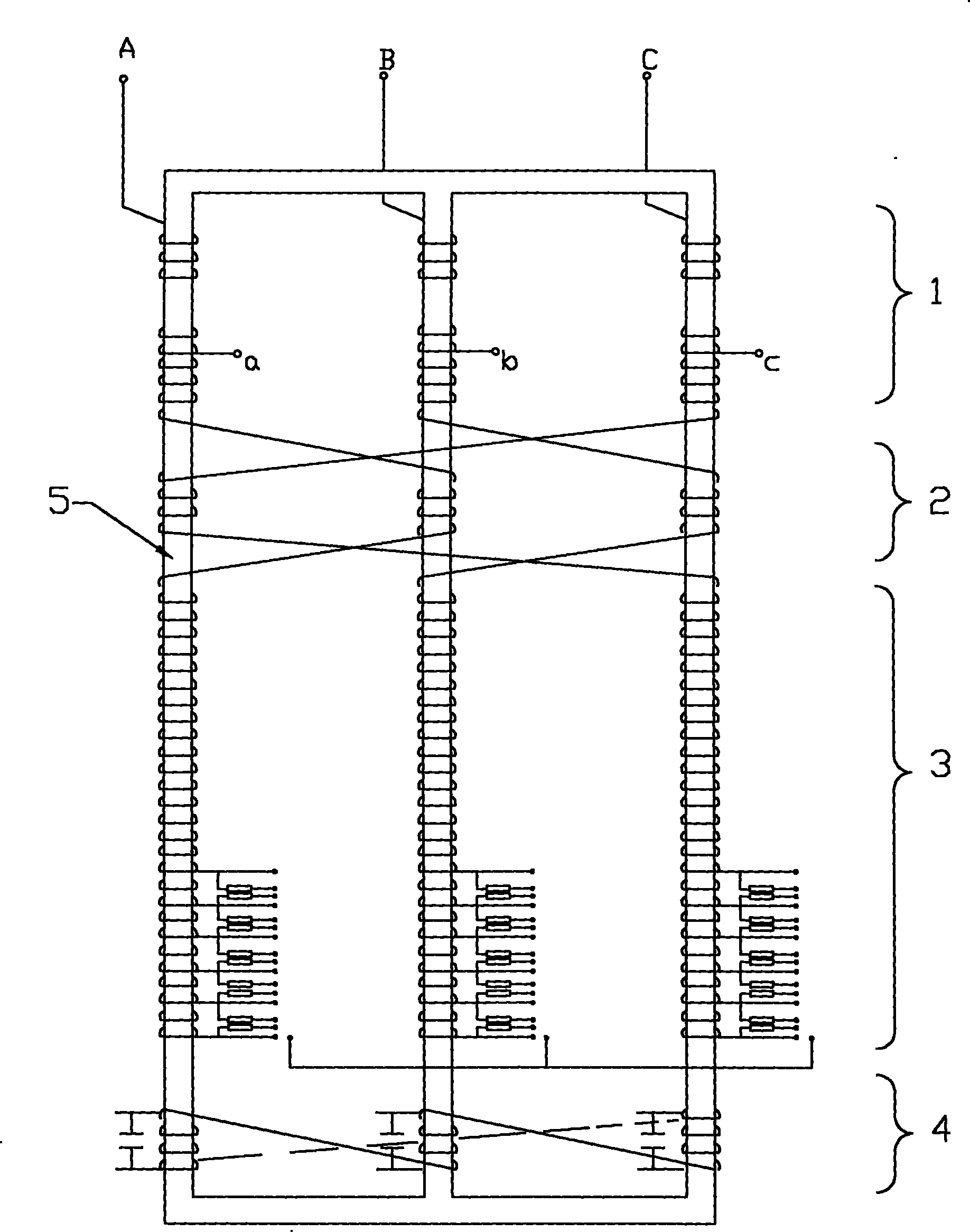

Image

  • Power economizer for low matching system
  • Power economizer for low matching system
  • Power economizer for low matching system

Examples


Embodiment Construction

[0060] The present invention will be further described below in conjunction with the accompanying drawings.

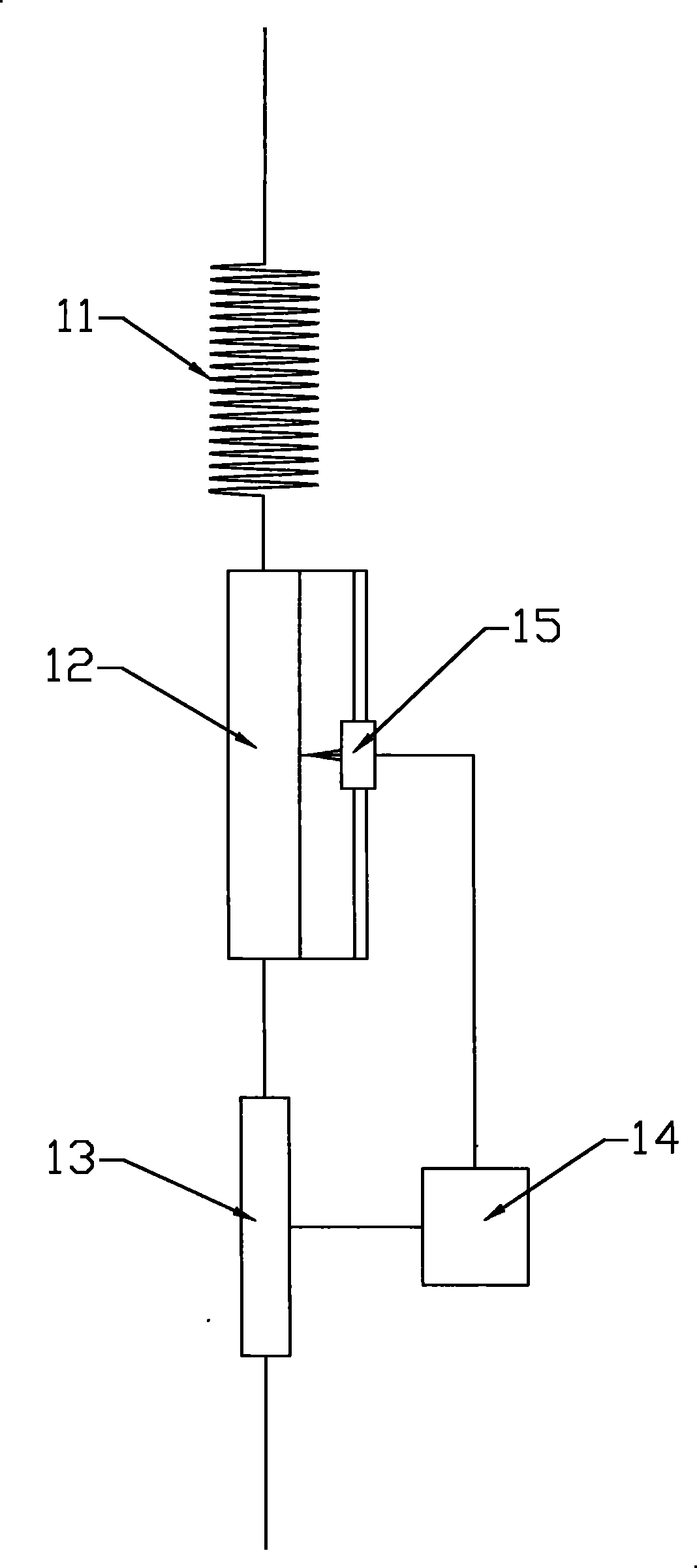
[0061] As shown in Figure 1, the energy saver of the low distribution system includes an automatic constant current incoming line resistor 1, an electromagnetic balance winding 2, an automatic constant voltage on-load adjustment device 3, a grid purification device 4 and an iron core 5, wherein:

[0062] The automatic constant current incoming line resistor 1 (see Fig. 2) is to connect the starting winding 11, the sliding wire rheostat 12 and the current transducer 13 in series, and the current transducer 13 is connected to drive the sliding wire rheostat 12 through the transmission mechanism. The active servo motor is the driver 15 , and a current sampling control module 14 is also connected between the driver 15 and the current transmitter 13 .

[0063] The automatic constant current incoming line resistor is connected to each line of the power distribution system (s...


PUM


Abstract

The invention discloses an energy saver of a low-voltage system and belongs to an electric energy saving device; in the prior art, the disadvantages of energy consumption and increasing extra copper loss of a motor exist; in the invention, in each phase alternating current of threephase alternating current, the starting winding of an automatic constant-current line-incoming impedor, the alternating current winding of an electromagnetic balance winding and the adjusting winding of an automatic constant-current on-load adjusting device are wound on an iron core in series, and the coils of a filtering inductor and the coils of the starting winding, the alternating current winding and the adjusting winding are wound on the iron in parallel; a wire leading-out terminal is extracted out betweenthe starting winding and the alternating current winding, and the other end of the starting winding is taken as a wire leading-in terminal. When in use, the wire leading-in terminal is connected witha power supply circuit and the wire leading-out terminal is connected with the electrical appliance. In a power supplying system, the energy saver of the low-voltage system is arranged, thus achieving the functions of energy saving and filtering and the like.

Description

technical field [0001] The invention belongs to an electric energy-saving device, in particular to an energy-saving device for a low distribution system connected in a circuit for energy saving. Background technique [0002] As we all know, when the adjacent lines have faults and interference, it will affect the voltage stability on the working lines, affect the normal work of various electrical equipment, and even fail to carry out production operations at all. [0003] When there are large-capacity equipment in the power distribution system, a large number of transient surges will be generated when they frequently switch working states, which will affect the working state and efficiency of other equipment. [0004] When a variety of equipment in the power distribution system starts frequently, it will generate 2-7 times the start-stop current, causing a great impact on the power grid and transformers, causing the temperature of the transformers and transmission lines to ri...

Claims


Application Information

Patent Timeline
Patent Type & Authority Patents(China)
IPC IPC(8): H02J3/00H02J3/01H02J3/38
CPCY02E40/40
Inventor 斯志光
Owner 诸暨市丰搏环保科技有限公司
Features
  • R&D
  • Intellectual Property
  • Life Sciences
  • Materials
  • Tech Scout
  • Unparalleled Data Quality
  • Higher Quality Content
  • 60% Fewer Hallucinations
Learn More